
Summary of High-voltage seven segment LED display driver with SPI interface
This article describes a driver board enabling large seven-segment LED displays (up to 24V) to interface with 5V microcontrollers. It solves the limitation of the MAX7219 chip, which cannot drive high-voltage segments directly. The design uses an SPI interface and specific voltage translation circuits to safely control displays requiring higher forward voltages than standard modules.
Parts used in the High-voltage Seven Segment LED Display Driver:
- MAX7219 device
- UDN2981A 8-channel source driver
- ULN2803 external sink lines
- 74HC540 eight channel logic inverter
- Potentiometer for HV adjustment
- Power supply unit providing regulated +5V
- Host microcontroller via 3-wire SPI bus
- Five inch seven segment LED modules
Seven segment LED displays are known to be resource and power hungry. But because they are visually so charming and readable from a far viewing distance and at a much wider viewing angle as compared to any other electronic displays, they are still hugely popular. The required number of I/O pins to drive the LED segments can be reduced significantly by using an additional dedicated hardware. For example, the MAXIM’s MAX7219 device allows you to interface 8 pieces of seven segment LED modules using only 3 I/O pins of Arduino or any other microcontroller.
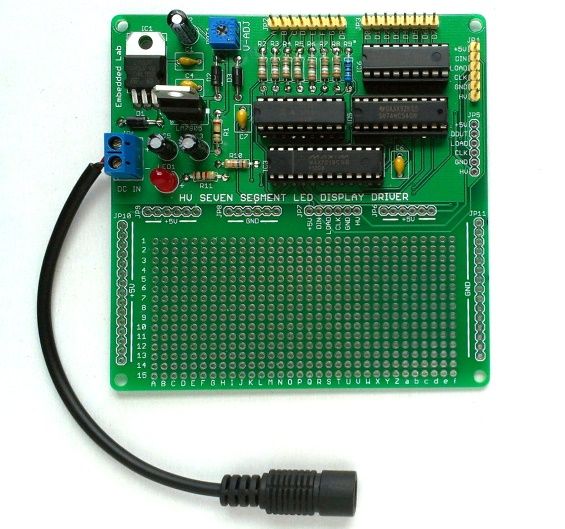
You can find details on the use of MAX7219 to drive seven segment LED displays in my previous projects 4-digit serial seven segment LED display (SPI7SEGDISP4.40-1R), 8-digit serial seven segment LED display (SPI7SEGDISP8.56-1R), and double-row 4-digit seven segment LED display (SPI7SEGDISP8.56-2R). Since MAX7219 operates at 5V, its output can drive LED segments with forward voltage less than 5V. I have successfully used MAX7219 IC with 1.5″ seven segment LED modules that carry two regular LEDs in series per segment. Inside larger seven segment LED modules, the display segments are made of multiple LEDs connected in series and parallel to provide sufficient light to illuminate the segment, and as such they require a higher forward voltage and more current to operate. Recently, I have designed this display driver board that can be used as a bridge in between larger seven segment LED displays (with segment forward voltage up to 24V) and a 5V microcontroller. On its input side is MAX7219 which receives the display data from the host microcontroller through a 3-wire SPI bus. – See more at:
Theory
This project uses the MAX7219 device on the input side to receive the display data from a host microcontroller through an SPI interface. The MAX7219 outputs cannot drive LED segments with forward-voltage above 5V. Therefore, an additional circuit is required to translate the TTL output levels of MAX7219 into appropriate high voltage signals required to operate the large seven segment LED modules. To illustrate I am using eight 5″ displays which require about 14V to drive segments ‘a’ through ‘g’ (each consists of two rows of 7 standard LEDs), and 6V to drive the DP segment (consists of 3 LEDs). The following figure shows the arrangement of multiple LEDs inside the display segments of the 5″ seven segment module I am using.
This project uses the MAX7219 device on the input side to receive the display data from a host microcontroller through an SPI interface. The MAX7219 outputs cannot drive LED segments with forward-voltage above 5V. Therefore, an additional circuit is required to translate the TTL output levels of MAX7219 into appropriate high voltage signals required to operate the large seven segment LED modules. To illustrate I am using eight 5″ displays which require about 14V to drive segments ‘a’ through ‘g’ (each consists of two rows of 7 standard LEDs), and 6V to drive the DP segment (consists of 3 LEDs). The following figure shows the arrangement of multiple LEDs inside the display segments of the 5″ seven segment module I am using.
Block diagram
The following block diagram explains the overall functionality of the board. The power supply unit provides a regulated +5V to power the logic chips, and a variable high voltage (HV) required to drive the LED segments. The value of HV can be adjusted as needed through a potentiometer. On the input side is MAX7219 chip which receives display data from a host microcontroller through a serial interface. In order to find more detail about the MAX7219 interface, visit MAX7219 based seven segment LED display. The output segment driver pins of MAX7219 are translated to high voltage signal lines using UDN2981A, which is a 8-channel source driver. In order to prevent the DIG0-DIG7 sink outputs of MAX7219 from any possible damage (or malfunctioning) due to high voltage signals applied to LED segments, external sink lines are created using ULN2803. Since the DIG0-DIG7 lines of MAX7219 are active low and ULN2803 inputs are active high, an eight channel logic inverter (74HC540) is used in between to make the two sets of signal lines compatible. Imagine a situation when outputs of UDN2981A (which is set by varying HV) is higher than the forward voltage of LED segments by more than 5V. If DIG0-DIG7 sinks are used directly without the arrangement discussed above, then no matter what is the output state of DIG0-DIG7, the LED segments will always be on. So the use of 74HC540 and ULN2803 as external sinks prevents this malfunctioning.
The following block diagram explains the overall functionality of the board. The power supply unit provides a regulated +5V to power the logic chips, and a variable high voltage (HV) required to drive the LED segments. The value of HV can be adjusted as needed through a potentiometer. On the input side is MAX7219 chip which receives display data from a host microcontroller through a serial interface. In order to find more detail about the MAX7219 interface, visit MAX7219 based seven segment LED display. The output segment driver pins of MAX7219 are translated to high voltage signal lines using UDN2981A, which is a 8-channel source driver. In order to prevent the DIG0-DIG7 sink outputs of MAX7219 from any possible damage (or malfunctioning) due to high voltage signals applied to LED segments, external sink lines are created using ULN2803. Since the DIG0-DIG7 lines of MAX7219 are active low and ULN2803 inputs are active high, an eight channel logic inverter (74HC540) is used in between to make the two sets of signal lines compatible. Imagine a situation when outputs of UDN2981A (which is set by varying HV) is higher than the forward voltage of LED segments by more than 5V. If DIG0-DIG7 sinks are used directly without the arrangement discussed above, then no matter what is the output state of DIG0-DIG7, the LED segments will always be on. So the use of 74HC540 and ULN2803 as external sinks prevents this malfunctioning.
For more detail: High-voltage seven segment LED display driver with SPI interface
-
How does the MAX7219 interface with the host microcontroller?
The MAX7219 receives display data from a host microcontroller through a 3-wire SPI bus. -
What limits the direct use of MAX7219 for large displays?
The MAX7219 outputs cannot drive LED segments with a forward voltage above 5V. -
Which component translates TTL output levels to high voltage signals?
The UDN2981A is used to translate the TTL output levels of the MAX7219 into appropriate high voltage signals. -
Why are ULN2803 components included in the circuit?
External sink lines using ULN2803 prevent damage or malfunctioning of the DIG0-DIG7 sink outputs due to high voltage signals. -
What is the function of the 74HC540 logic inverter?
The 74HC540 makes the signal lines compatible because MAX7219 outputs are active low while ULN2803 inputs are active high. -
How is the high voltage level adjusted on this board?
The value of the variable high voltage can be adjusted as needed through a potentiometer. -
What happens if DIG0-DIG7 sinks are used without the proposed arrangement?
If used directly, the LED segments will always be on regardless of the output state of the DIG0-DIG7 lines. -
Can this driver board handle displays with up to 24V forward voltage?
Yes, the designed display driver board can be used as a bridge for larger seven segment LED displays with segment forward voltage up to 24V.
