Summary of How to Use the Dragon Rider 500 With Your AVR Dragon
This article provides a crash course on using the Dragon Rider 500 interface board with the Atmel AVR Dragon programmer. It covers software setup with AVRdude, programming various microcontrollers like the ATtiny2313 and ATmega8, and configuring jumpers for different pin counts. The guide details projects including blinking LEDs, driving an LCD screen, building a digital clock with buttons, and performing High Voltage Parallel Programming to recover chips with incorrect fuse settings. It also explains how to expand prototyping capabilities by connecting breadboards to the board's headers.
Parts used in the Dragon Rider 500 Projects:
- Dragon Rider 500 Interface Board
- AVR Dragon Programmer
- ATtiny2313 Microcontroller
- ATmega8 Microcontroller
- LCD Add-on Screen
- Push Buttons (SW1, SW2)
- Ribbon Cables
- Breadboards
- Jumper Wires
- USB Cable
This instructable is a crash course in how to use some of the features of the Dragon Rider 500 from Ecros Technologies. Please be aware that there is a very detailed User’s Guide available on the Ecros website.
The Dragon Rider is a interface board for use with an AVR microcontroller programmer called the AVR Dragon by Atmel.
For more information:
Atmel’s Wesite:
http://www.atmel.com/
AVR Dragon link:
http://www.atmel.com/dyn/products/tools_card.asp?tool_id=3891
Dragon Rider 500 by Ecros Technology:
http://www.ecrostech.com/AtmelAvr/DragonRider/index.htm
Dragon Rider 500 assembly Instructable:
https://www.instructables.com/id/Assembling-the-Dragon-Rider-500-for-use-with-the-A/
Learn all about the AVR microcontrollers:
http://www.avrfreaks.net
This instructable may grow with time so check back now and again!
Step 1: AVR Dude
You need some programming software in order to use the AVR Dragon for programming. I use AVRdude with the Ubuntu operating system (linux) and I’m very happy with the results.
This instructable will not deal with the intricacies of programming software. If you do not know how to set-up or use programming software, check this instructable out to bring you up to speed:
https://www.instructables.com/id/Getting-started-with-ubuntu-and-the-AVR-dragon/
My guess is that if you have purchased and assembled a Dragon Rider 500 you already know how to program a chip with the AVR Dragon….. onward!
Step 2: ATtiny2313 – Blink the LEDs
Let’s program an ATtiny2313 which is a 20-pin microcontroller.
The Dragon Rider 500 has sockets for several different sized AVR microcontrollers. These include: 8, 20, 28, and 40 pin sockets. Depending on which socket you use, jumpers on the Dragon Rider board must be set differently.
Jumper Settings
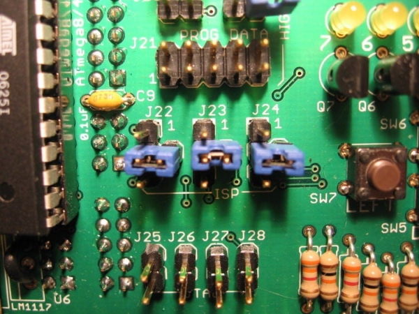
Set the jumpers on the Dragon Rider so that the shunts connect the following pins. (pin4 is the center pin for J22-J-24)
Pins:
J5 – 23
J6 – 23
J7 – 12
J16 – 23
J22 – 41
J23 – 41
J24 – 41
This is a basic setup that allows for ISP (In System Programming).
Blinky Blinky
Programming does no good unless you have something to program. I have written a very short code example to blink the Dragon Rider’s LED’s one at a time.
Use a ribbon cable to connect the LED header (J29) to the PortB header (J2).
Programming
I’ve included the C file as well as a makefile and the hex file. Like I mentioned in the intro, I cannot cover the software side of programming in the Instructable. Program like you would for the AVR Dragon, as the Dragon Rider doesn’t alter the software side of things at all.
Step 3: Using the LCD Add-on
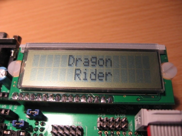
Here’s a simple way to use the LCD Add-on. This will write “Dragon Rider” to the LCD screen.
Hardware:
- ATtiny2313
- R/W Jumper: R/W should be connected to “BIT1” on the Dragon Rider Board (See explaination in the Assembly Instructable)
- J23: This jumper must be installed for ISP programming but then removed for the LCD to function properly.
- Connect LCD to PORT B using ribbon cable (J31 to J2)
Software
I am using Peter Fleury’s LCD library to drive the LCD in 4-bit mode. Check out Peter’s Homepage to download the library.
You will need to make sure that lcd.c is compiled with your code and that you make the following changes to lcd.h:
- We are using the internal RC oscillator so XTAL needs to be set for 1MHz:
- Port settings need to be adjusted to PORTB:
- Pinout for 4 data lines needs to be adapted:
- Pinout for RS, RW, and E needs to be adapted:
The main program is very simple thanks to the work Peter Fleury did in his LCD library.
CODE:
#include <avr/io.h>#include "lcd.h"int main(void){ lcd_init(LCD_DISP_ON); //Initialize LCD with the cursor off lcd_clrscr(); //Clear the LCD screen lcd_gotoxy(5,0); //Move cursor to this location lcd_puts("Dragon"); //Put this string on the LCD lcd_gotoxy(6,1); //Move cursor to this location lcd_puts("Rider"); //Put this string on the LCD for (;;) { // Do nothing forever (Message already displayed on LCD) }}
Code Attached
The code attached includes Peter Fleury’s LCD library (lcd.c and lcd.h) with his permission. Thank you Peter! The only alteration I have made to it is to set the proper pins in the Defines. Please visit his site to download the package: http://www.jump.to/fleury
I have also included a makefile that I use written by Eric B. Weddington and, Jorg Wunsch. I sent a PM to Jorg over at avrfreaks.net but never received a response from him. There are a few changes in the makefile to tailor to using Linux and the Dragon. Thank you to you both, please set me know your preferences on me sharing your work.
Step 4: 28-pin UC ISP Programming (ATmega8)
The next project demontration will utilize an ATmega8 which is a 28-pin avr. Here is the the basic jumper set for ISP programming the 28-pin microcontrollers.
Jumper Settings
Set the jumpers on the Dragon Rider so that the shunts connect the following pins. (pin4 is the center pin for J22-J-24)
Pins:
J11 – 23
J12 – 23
J13 – 12
J16 – 23
J22 – 42
J23 – 42
J24 – 42
Technical Information
- Connecting J11 and J12 in this fashion allows you to use those pins as I/O pins. The alternative would be to route these pins to make a connection with the external crystal.
- Connecting J13 in this fashion allows us to use it as the reset pin. The alternative would route this pin to the PORTC header for use as an I/O pin. (this would have many drawbacks, including the inability to program this chip using ISP).
- J16 & J22-J24 are connected in this fashion to route the appropriate pins (Reset, MISO, MOSI, and SCK) to the ISP header of the AVR Dragon.
Step 5: Advanced LCD and Button Usage: the Big Clock
This is a fun project that makes use of the LCD screen and buttons. We will be dealing with Real Time Clock functions and custom characters on the LCD.
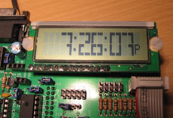
In the picture at the bottom you can see the time 7:26:07pm displayed in large numbers on the LCD screen. Each number is using a 2×2 grid of the characters display to show the large number. This utilizes a font originally written by Xtinus for the XBMC project.
The buttons are used to set the clock. Left increments the hours, Up increments the minutes, Right toggles between 12 and 24-hour time, and Enter resets the seconds to zero.
The clock doesn’t keep very good time as we are using the very inaccurate internal oscillator, but this program can easily be altered to use a much more accurate external crystal. See this in action in the video below.
An explaination of how this code works is in order, but I don’t have the time right now.
For now, connect the LCD header (J31) to PORTD (J4) and the button header (J30) to PORTB (J2). Make sure you have both SW1 and SW2 in the off position. Connect the AVR Dragon to a usb cable and plug the other end of that cable into your computer. Turn on SW2 and program the ATmega8 with the programming software of your choice (hex file below; fuses burnt to factory settings).
NOTE: In order to utilize the Left and Up buttons you will need to remove the shunts from J22 and J24, do this while the power is off.
Step 6: High Voltage Programming
I have used the High Voltage Parallel Programming to resurrect an ATtiny2313 that I set the wrong fuse settings on. I needed it a second time when working on this instructable because I accidentally wrote the lfuse setting I wanted to the hfuse register….. ooops. High Voltage parallel programming is a handy tool to have at your disposal!
Below are a lists of my jumper settings:
USE AT YOUR OWN RISK, THIS TYPE OF PROGRAMMING CAN DAMAGE YOUR HARDWARE IF YOU DON’T KNOW WHAT YOU’RE DOING!!
High Voltage Parallel Programming:
ATtiny2313 in socket U3:
SW1 – OFF
SW2 – ON
J5, J6, J7 – connect pin1 and pin2
XTAL1 – connect pin1 and pin2
J16 – Connect pin1 and pin2
2×5 IDC Cables: PROG_CTRL to PORT D, PROG_DATA to PORT B
All other jumpers unconnected (J8-J13, J18, J19, J20, J22-J28, J24)
For other chips you should be able to figure out the settings you need from Atmel’s user guide for their STK500.
Step 7: Expanding Beyond the Board

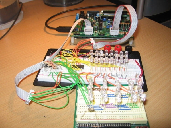
I find it quite easy to interface with a breadboard. This allows for a lot more flexibility in prototyping and developing code at the same time.
Below you will see a couple of breadboards connected to the Dragon Rider. I connect up the ribbon cables to the appropriate ports at one end. At the other I use jumper wires to connected the proper ICD conductor with the breadboards.
Step 8: Conclusion
There is much more that could be involved in this Instructable. Just tonight I complete an adapter that allows you to use the 6-pin programming header without removing the dragon from the Dragon Rider. I’ll be putting information on how to construct one yourself… coming soon.
If you have other things you think need to be added leave a comment.
Source: How to Use the Dragon Rider 500 With Your AVR Dragon
- What software is recommended for programming the AVR Dragon?
The author uses AVRdude with the Ubuntu operating system. - How do you configure jumpers for ISP programming an ATtiny2313?
Connect J5, J6, J7, and J16 to pin 23; connect J22, J23, and J24 to pin 41. - Can the Dragon Rider board alter the software side of programming?
No, the Dragon Rider does not alter the software side of things at all. - Which library is used to drive the LCD in 4-bit mode?
Peter Fleury's LCD library is used to drive the LCD. - How are the buttons configured in the Big Clock project?
Left increments hours, Up increments minutes, Right toggles time format, and Enter resets seconds. - What causes the clock to not keep accurate time?
The program uses the very inaccurate internal oscillator. - How can you fix a chip with wrong fuse settings?
You can use High Voltage Parallel Programming to resurrect the chip. - What is required to utilize the Left and Up buttons in the clock project?
You must remove the shunts from J22 and J24 while the power is off. - How can you expand prototyping beyond the board itself?
You can interface with breadboards using ribbon cables and jumper wires.