Summary of How To Write a Simple Bootloader For AVR In C language
This article explains how to write a simple Boot-Loader for the ATMEGA16 microcontroller in C. The Boot-Loader initializes hardware peripherals like USART, an LED, and a 4-bit LCD before loading an application code from the internal EEPROM into the flash memory using Self Programming Mode (SPM). It details the use of AVR Studio 4, USBASP programmer, and specific header files like `` and ``.
Parts used in the Simple Boot-Loader for AVR:
- ATmega16 microcontroller
- 4-bit LCD display
- LED
- Resistor
The BootLoader is a code which executes when a microcontroller is powered ON or reset. It basically sets an environment for the application code to execute. It is the Boot-Loader that sets the hardware and loads the application code from any storage medium or received through external communication and let the application to execute. Thus a Boot-Loader has to perform the following basic function : Initialize the controller peripherals,
Initialize the devices in the board, Allow an option for the user to select from the available applications to load, Load the selected application, Let the application code to execute. Apart from the above mentioned functions some Boot-Loaders can perform many other functions and there are Boot-Loaders which don’t perform all these functions like provide option to select the required application etc. The Boot-Loader codes in microcontrollers are actually very small and simple compared to the Boot-Loaders in advanced devices like PC. In most of the microcontroller the functionality of a Boot-Loader is limited only to set the initial clock and other settings for the microcontroller, load an application binary from the serial port etc.In an AVR microcontroller writing a Boot-Loader code is comparatively easy, since any code which is written to the BLS section of the flash memory can have complete access to the hardware of the microcontroller. The flash memory of the AVR microcontroller is divided into two sections; an Application flash section and a Boot-Loader section (BLS).
Any code which executes from the BLS can use Self Programming Mode (SPM). Using the SPM feature a code from the BLS section can read or write the entire flash memory including the BLS section where the code is running from. This feature can be used to load any application code binary to the flash memory and let it execute. The required initialization of the controller peripherals like USART, port bits etc. and the initialization of the external devices like LCD etc. can be done from the BLS itself before loading the application code.
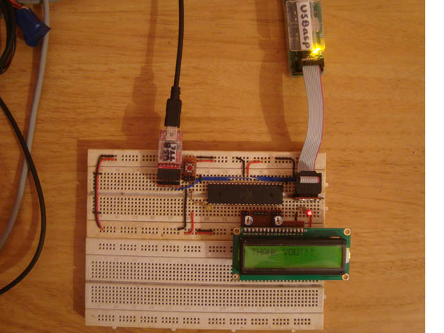
In this project discuss how to write a simplest Boot-Loader code for the AVR microcontroller which can initialize the peripherals like USART, LED port and initialize a 4 bit LCD connected to the controller and then load any application which has been flashed into the built-in EEPROM of the microcontroller. The microcontroller used in this project is ATMEGA16, and the programmer used is USBASP. The AVR studio 4 is used as the IDE and the burner software used is AVR-BURNO-MAT.
The AVR flash memory is divided into two sections namely the application section and the Boot-Loader section (BLS). In case of the ATMEGA16 it has 16 KB of flash memory of which the 15KB is application section and the remaining 1KB is BLS. The memory architecture of the ATMEGA16 is shown in the following figure;
The code for both the BLS and application section can be written as normally does and there is no much difference. The only thing to be careful about is the size of the code binary. It should not be more than 1KB, otherwise it won’t be able to code programmed into the BLS. The project on AVR BLS coding discusses how to program a simple code into the BLS of ATMEGA16 microcontroller with the help of AVR studio as IDE, USBasp as the programmer and AVR-Burnomat as the burner software.
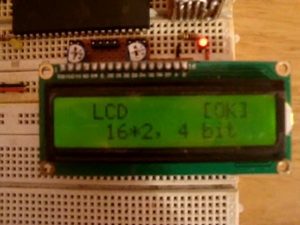
In this particular project the Boot-Loader is coded to perform UART initialization along with a simple LED pin initialization and also an external hardware initialization of the 4 bit LCD. Hence the application codes does not require those codes in them, still they works because before executing the application codes the initialization functions will be executed by the Boot-Loader.
The BLS code has the initialization functions which should not be there in the application codes. The initialization functions used in the Boot-Loader code for this project are given below;
| Function | Description |
| void lcd_init ( void ) | Initialize the LCD in 4 bit mode |
| void usart_init ( void ) | Initialize the usart in 9600 baud rate with transmission and reception enabled |
| DDRD |= 0x80; | Initialization of the LED pin as output |
Any application code can directly use the following function calls to access the USART, LCD and LED without their initializing functions anywhere in their code.
| Function | Description |
| lcd_clear () | Clear the LCD |
| lcd_string () | Display a string in the LCD |
| usart_send_string () | Send a string via usart |
| PORTD &= 0x7F; | Turn ON the LED |
| PORTD |= 0x80; |
Turn OFF the LED |
The hardware initialization before executing the application code is explained in detail in a projecton Initializing hardware from AVR BLS.
The major function of the Boot-Loader is load a code binary form storage medium or which can be received through the external communication with other devices to the flash memory. The SPM feature available for the code executing from the BLS helps in loading an application code binary to the flash memory. The task of writing the BLS code with SPM has been made simple by the APIs available in the header file <avr/boot.h>. The following are the important APIs available in the header file which helps in the SPM.
| FUNCTION | DESCRIPTION | PARAMETER |
| boot_page_erase (address) | Erase the flash page that is referred by address | A byte address in flash |
| boot_page_fill (address, data) | Fill the Boot-Loader temporary page buffer for flash address with data word | The address is a byte address. The data is a word |
| boot_page_write (address) | Write the Boot-Loader temporary page buffer to flash page that contains address | Byte address in flash |
Fig. 5: Important APIs in AVR
The steps required to do the SPM on the application flash memory is explained in a project on using SPM in AVR flash to flash programming.
In this particular project the Boot-Loader is coded in such a way that it will try to load any application code binary which has been loaded into the built-in internal EEPROM of the AVR microcontroller. The APIs available in the <avr/eeprom.h> is used to read the data bytes from the EEPROM and with the help of APIs from the <avr/boot.h> the data bytes are stored into a temporary buffer and then flashed into the application section of the flash memory.
The API provided by the <avr/eeprom.h> to read the data bytes from the built-in EEPROM of the AVR microcontroller is;
uint8_t eeprom_read_byte (const uint8_t *p)
| FUNCTION | DESCRIPTION | PARAMETER |
| uint8_t eeprom_read_byte (const uint8_t *p) | The function returns one data byte which is stored in the EEPROM address referred by the pointer p | The pointer refers to the EEPROM address from which the data byte need to be read |
Fig. 6: API <avr/eeprom.h> to read data bytes from in-built EEPROM of AVR microcontroller
With the help of the above discussed APIs from both <avr/boot.h> and <avr/eeprom.h> one can use the SPM feature of the AVR microcontroller to write a Boot-Loader code which can load an application which has been programmed into the built-in EEPROM of the AVR microcontroller. For that one should follow the steps mentioned below which are explained in a project on using SPM in AVR EEPROM to flash programming.
{C}{C}{C}{C}{C}{C}{C}{C}{C}{C}{C}{C}{C}{C}· {C}{C}{C}{C}{C}{C}{C}{C}{C}{C}{C}{C}{C}{C}Step: 1 Erase the flash page which is about to write into
{C}{C}{C}{C}{C}{C}{C}{C}{C}{C}{C}{C}{C}{C}· {C}{C}{C}{C}{C}{C}{C}{C}{C}{C}{C}{C}{C}{C}Step: 2 Store the code binary which are read from the EEPROM into a temporary buffer before write into a flash page
{C}{C}{C}{C}{C}{C}{C}{C}{C}{C}{C}{C}{C}{C}· {C}{C}{C}{C}{C}{C}{C}{C}{C}{C}{C}{C}{C}{C}Step: 3 Program the filled temporary buffer into the already erased flash page
After performing the above three steps the Boot-Loader can then make a jump using the statement
asm ( “jmp 0x0000” );
to the application code section and let the newly programmed application to execute.
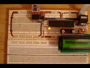
Flash the Boot-Loader code to the BLS first any small sized application code to the EEPROM memory using the steps explained in the previous project on LED blinking from BLS of AVR. Once the EEPROM programming has completed and when the controller resets the Boot-Loader will start executing. Once can observe that it is performing the initialization functions and is loading the application from the built-in EEPROM.
Project Source Code
###
#define _LCD_H #ifndef F_CPU #define F_CPU 8000000 #endif #include<avr/io.h> #include<util/delay.h> #include<inttypes.h> #define rs PA0 #define rw PA1 #define en PA2 void lcd_init(); void dis_cmd(char); void dis_data(char); void lcdcmd(char); void lcddata(char); void lcd_clear(void); void lcd_2nd_line(void); void lcd_1st_line(void); void lcd_string(const char *data); void lcd_string(const char *data) { for(;*data;data++) dis_data (*data); } void lcd_clear(void) { dis_cmd(0x01); _delay_ms(10); } void lcd_2nd_line(void) { dis_cmd(0xC0); _delay_ms(1); } void lcd_1st_line(void) { dis_cmd(0x80); _delay_ms(1); } void lcd_init() // fuction for intialize { DDRA=0xFF; dis_cmd(0x02); // to initialize LCD in 4-bit mode. dis_cmd(0x28); //to initialize LCD in 2 lines, 5X7 dots and 4bit mode. dis_cmd(0x0C); dis_cmd(0x06); dis_cmd(0x80); dis_cmd(0x01); _delay_ms(10); } void dis_cmd(char cmd_value) { char cmd_value1; cmd_value1 = cmd_value & 0xF0; //mask lower nibble because PA4-PA7 pins are used. lcdcmd(cmd_value1); // send to LCD cmd_value1 = ((cmd_value<<4) & 0xF0); //shift 4-bit and mask lcdcmd(cmd_value1); // send to LCD } void dis_data(char data_value) { char data_value1; data_value1=data_value&0xF0; lcddata(data_value1); data_value1=((data_value<<4)&0xF0); lcddata(data_value1); } void lcdcmd(char cmdout) { PORTA=cmdout; PORTA&=~(1<<rs); PORTA&=~(1<<rw); PORTA|=(1<<en); _delay_ms(1); PORTA&=~(1<<en); } void lcddata(char dataout) { PORTA=dataout; PORTA|=(1<<rs); PORTA&=~(1<<rw); PORTA|=(1<<en); _delay_ms(1); PORTA&=~(1<<en); } #endif
###
Project Source Code
###
#define rs PA0 #define rw PA1 #define en PA2 #include <avr/io.h> #include <util/delay.h> void dis_data(char data_value); void usart_putch(unsigned char send); unsigned int usart_getch(); int main ( void ) { int i; unsigned int c; //——– led test ———–// DDRD |= 0x80; for ( i =0; i < 5; i ++ ) { PORTD = ~PORTD; _delay_ms ( 500 ); } //——– led test ———–// //—– usart + lcd test ——-// while ( 1 ) { c = usart_getch(); usart_putch( ( unsigned char ) c ); dis_data( ( char ) c ); } //—– usart + lcd test ——-// } void dis_data(char data_value) { char data_value1; data_value1=data_value&0xF0; PORTA=data_value1; PORTA|=(1<<rs); PORTA&=~(1<<rw); PORTA|=(1<<en); _delay_ms(1); PORTA&=~(1<<en); data_value1=((data_value<<4)&0xF0); PORTA=data_value1; PORTA|=(1<<rs); PORTA&=~(1<<rw); PORTA|=(1<<en); _delay_ms(1); PORTA&=~(1<<en); } void usart_putch(unsigned char send) { while ((UCSRA & (1 << UDRE)) == 0); // Do nothing until UDR is ready.. // for more data to be written to it UDR = send; // Send the byte } unsigned int usart_getch() { while ((UCSRA & (1 << RXC)) == 0); // Do nothing until data have been received and is ready to be read from UDR return(UDR); // return the byte }
###
Circuit Diagrams
| Circuit-Diagram-of-How-To-Write-Simple-Bootloader-For-AVR-In-C-language |
Project Components
Project Video
For more detail: How To Write a Simple Bootloader For AVR In C language
- What is the primary function of a Boot-Loader in a microcontroller?
It initializes controller peripherals, allows user selection of applications, loads the selected application, and lets it execute. - How does the ATMEGA16 divide its flash memory?
The 16 KB flash memory is divided into a 15 KB application section and a 1 KB Boot-Loader section (BLS). - Which feature allows BLS code to read or write the entire flash memory?
The Self Programming Mode (SPM) feature enables the code in the BLS section to access all flash memory including itself. - Can application codes initialize hardware if the Boot-Loader already did it?
No, the application codes do not require initialization functions because the Boot-Loader executes them before running the application. - Which header file provides APIs for Self Programming Mode operations?
The header file contains important APIs like boot_page_erase, boot_page_fill, and boot_page_write. - How is data read from the internal EEPROM in this project?
The eeprom_read_byte function from the header is used to read data bytes from the built-in EEPROM. - What command jumps execution to the application code section after loading?
The statement asm jmp 0x0000 is used to jump to the application code section and let it execute. - What software tools are recommended for writing and burning this Boot-Loader?
The article recommends using AVR Studio 4 as the IDE, USBASP as the programmer, and AVR-Burnomat as the burner software.