Summary of I2C Blynk Car With Attiny85 and M5StickC
This project builds an I2C DC motor drive using a DigiSpark ATTiny85 and an Arduino quad motor shield, controlled by an M5StickC running a Blynk joystick app over Wi-Fi to operate a small RC car. The M5StickC sends direction/speed commands via I2C to the ATTiny85, which drives four DC gear motors through the motor shield; power regulation and wiring are done with an LM2596 step-down module and protoboards.
Parts used in the I2C Blynk Car With Attiny85 and M5StickC:
- M5StickC
- DigiSpark ATTiny85
- Quad DC Motor Driver Shield for Arduino (DFRobot)
- 4 x Small DC Gear Motors with Wheels (reused CD/DVD motors or geared motors)
- LM2596S 3A Adjustable Step-down DC-DC Power Supply Module
- 2 x Double Sided DIY Protoboard Circuit 7x9cm
- Arduino Uno Protoshield
- 2 Slot Battery 18650 Holder
- 2 x Rechargeable Li-ion Battery 18650
- Male and Female Header pins (sets)
- 4 x Copper Standoff Spacers 20mm
- 8P/16P Rainbow Ribbon Cable (1 meter)
- 2 x R10K pull-up resistors
- XH2.54mm – 4P 10cm Wire Cable Double Connector
- Grove Connector
- Two Core Power Cable (1 meter)
- Cable spiral wrap, bolts and nuts
- Power switch
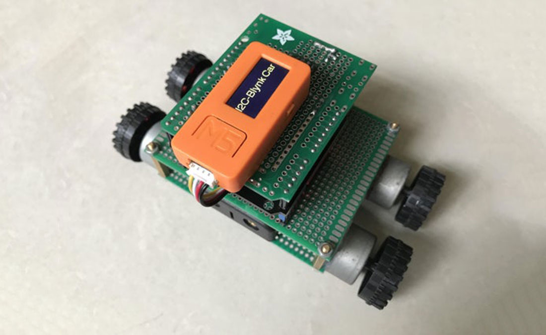
This project shows you how to build your own I2C DC motor drive using a DigiSpark Attiny85 plus Arduino motor shield. To test its operation, I made a small RC car which used an M5StickC & connected to Blynk App. to communicate with this drive via the I2C protocol.
Please check my introduction video before getting started.
Step 1: Supplies
First of all, I would like to thank the JLCPCB for supporting me on this project. If you have a PCB project, please visit the JLCPCB website to get exciting discounts and coupons as follows:
- JLCPCB PCB Prototype only $2.
- Get $24 Register Coupon here: jlcpcb.com/cyt
a. Main materials:
⦾ 1pcs x M5StickC.
⦾ 1pcs x DigiSpark ATTiny85.
⦾ 1pcs x Quad DC Motor Driver Shield for Arduino.
⦾ 4pcs x Small DC Gear Motor with Wheel. I’ve reused 4pcs x Micro DC Motor in the CD/DVD players and 4 wheels from toy cars, but it’s better to go with geared motors with wheel.
⦾ 1pcs x LM2596S 3A Adjustable Step-down DC-DC Power Supply Module.
⦾ 2pcs x Double Sided DIY Protoboard Circuit 7x9cm.
⦾ 1pcs x Arduino Uno Protoshield.
⦾ 1pcs x 2 Slot Battery 18650 Holder.
⦾ 2pcs x Rechargeable Li-ion Battery 18650.
⦾ 4pcs x Male & Female Header.
⦾ 4pcs x Copper Standoff Spacers 20mm.
⦾ 1 meter x 8P/16P Rainbow Ribbon Cable.
⦾ 2 pcs x R10K.
⦾ 1pcs x XH2.54mm – 4P 10cm Wire Cable Double Connector.
⦾ 1pcs x Grove Connector.
⦾ 1 meter x Two Core Power Cable.
⦾ Cable spiral wrap, bolts and nuts.
b. Tools:
⦾ Hot glue gun.
⦾ Soldering machine.
Step 2: Schematic
Main control components include: M5StickC, DigiSpark Attiny85, DFRobot Quad DC Motor Driver Shield for Arduino. And their connection is as below:
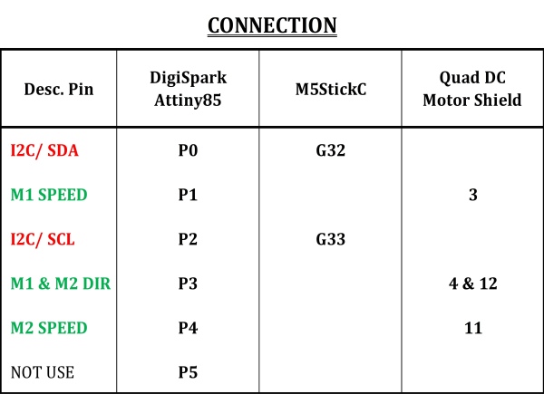
I used two communications in this project to control four DC motors of a RC car:
- M5StickC gets Blynk joystick command from smartphone via WIFI and converts it to car direction and speed.
- After that M5StickC transmits these converted commands to Attiny85 via I2C protocol. Finally, after receiving command, Attiny85 send its output signals to Quad motor shield to control direction and speed of car DC motors.
Notes:
- In the schematic, I used 2 pull-up resistors R10K on the SDA and SCL line.
- For the quad motor shield, I connected each group consisting of 2 DC motors in parallel at the M1 & M2 screw terminals. DIR signal of motor M1 & M2 has been connected together at motor shield pin 4 & 12. So I have controlled four DC motors with only 3 signals.
Step 3: Car Assembly
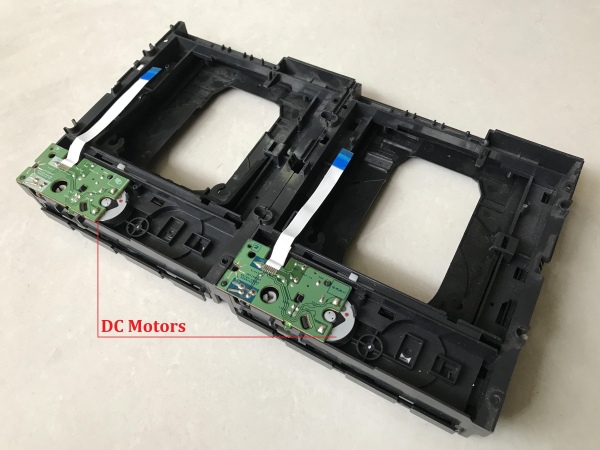
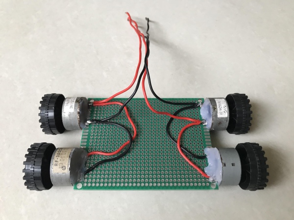
After using stepper motors for mini CNC projects, there are still some DC motors left in the CD/DVD player. They are used to insert or eject CD/ DVD plastic tray.
I disassembled four DC motors, soldered them on the double sided protoboard 7x9cm.
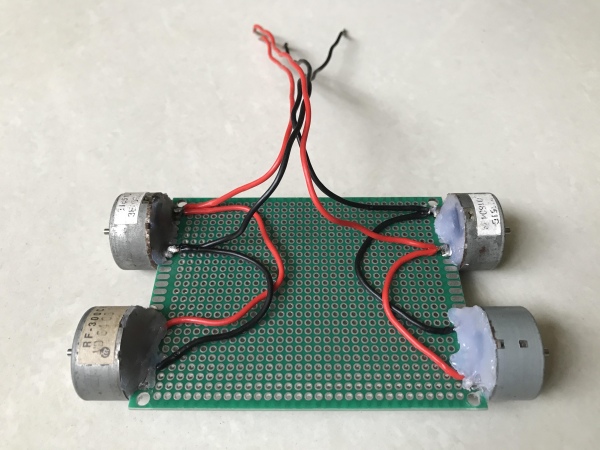
I found some wheels from small toy cars that have a center bore equal to the 2mm motor shaft diameter.
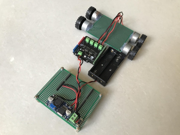
I used another protoboard 7x9cm then soldered on it a step-down power supply module LM2596, a power switch, a 2-pin screw header and 4 male header groups that match correspondingly to all the pins of the Quad DC Motor Shield for Arduino.
The LM2596 output terminals were connected to male headers at pin 5V and GND. It is used to power all the control circuits after I stack all the boards on these headers.
I connected wires for battery holder, module LM2596, motor shield power supply and 4 DC motors.
The main control circuit was soldered on an Arduino protoshield following the schematic on previous step, as follow:
⦾ Protoshield bottom includes: Attiny85 header (black), 4-pins I2C header (white) and motor shield headers (4 group – black).
⦾ Protoshield top includes: M5StickC 8 pin-header.
Source: I2C Blynk Car With Attiny85 and M5StickC
- What is the main control flow of the RC car?
M5StickC receives joystick commands from the Blynk app over WIFI, converts them to direction and speed, then sends them via I2C to the ATTiny85 which outputs signals to the quad motor shield to drive the motors. - Can four DC motors be controlled with only three signals?
Yes; the project connects pairs of motors in parallel and ties DIR signals of M1 and M2 together at motor shield pins 4 and 12 to control four motors with three signals. - Do I need pull-up resistors for I2C in this project?
Yes; the schematic uses two R10K pull-up resistors on the SDA and SCL lines. - How is power regulated for the control circuits?
An LM2596 step-down module is soldered on a protoboard and its 5V output is connected to male headers to power the control circuits when boards are stacked. - What motors were used for the car?
Four small DC motors salvaged from CD/DVD players were used, paired with wheels from toy cars; the guide recommends geared motors with wheels for better results. - How are the boards physically connected?
The ATTiny85 and M5StickC headers and motor shield headers are soldered onto an Arduino protoshield, and boards are stacked on matching male header groups. - Is the M5StickC connected to the ATTiny85 directly?
Yes; M5StickC transmits commands to the ATTiny85 via the I2C protocol using a 4-pin I2C header. - What wiring is used between batteries, regulator, and motors?
Wires connect the battery holder, LM2596 module, motor shield power supply, and the four DC motors as shown in the assembly; LM2596 output goes to 5V and GND headers.