Executive Summary
This UCF Senior Design project aims to address the need for an automated plant care device for homeowners, justifying its importance in various scenarios. Notably, homeowners who are away and have cherished plants often lack a reliable way to ensure their plants receive the necessary care. As a solution, we propose an Indoor Plant Monitoring System (IPMS) as an appealing alternative to existing options.
The IPMS will offer essential features for the autonomous management of light and water resources for unattended plants. These features, defined in the system specifications, encompass the elimination of manual on-site care, automatic resource application, extended operational capability, adaptability to diverse plant requirements, user-friendly interfaces, environmental sensing, remote accessibility, and user-friendliness.
Market requirements include considerations of cost, utility, ease of operation, reliability, duration of operation, durability, and appearance. The system specifications translate into engineering requirements involving power, size and weight, resource utilization rate, design complexity, sensor accuracy, operational range, and lifespan. These engineering requirements are integrated with the marketing needs through a conventional “House of Quality” approach, which helps determine the importance and prioritization of requirements.
The target engineering parameters for the IPMS encompass a minimum operation period of 14 days with over 90% reliability, a broad range of adjustment (90%), a compact single-board design weighing under one pound, and a minimum lifespan of five years without failures.
The project encompasses both hardware and software components. The hardware includes an ATmega 328 microprocessor integrating sensors for temperature, soil moisture, light, and humidity. It also incorporates WiFi and Bluetooth modules for the user interface. The software comprises an internet-based user interface for configuring operational parameters, as well as microprocessor code to interpret sensor inputs and control resource application as needed.
The estimated budget for the project ranges from $150 to $487, with the largest expenses attributed to peripheral items such as batteries, containers, lighting, and materials required for system development.
Detailed specifications for the major components are provided, along with a preliminary software design. The project schedule outlines milestones from spring to summer 2021, with a targeted project completion date in August 2021.
Furthermore, alternative project ideas are explored and assessed, with a description of the tentative selection of plants for the proof of concept.
1. Introduction:
Many individuals enjoy traveling and spending quality vacation time with their loved ones. However, a common concern arises when they leave their plants unattended at home. There are self-watering plant designs available in the market that maintain soil moisture by soaking the base of the plant pot. However, these designs lack a monitoring system to assess individual plant watering needs and light exposure.
Alternatively, many people resort to estimating or guessing the amount of water to leave for their plants before leaving the house to prevent them from drying out. Some may even seek help from others to visit their homes and water the plants, while others leave the plants to fend for themselves. In some instances, individuals attempt DIY irrigation systems guided by tutorials on websites like “youtube.com.”
This is where the Indoor Plant Maintenance System (IPMS) steps in to provide a solution. The IPMS aims to grant users access to crucial plant care information from any location worldwide. Its primary focus is on small to medium-sized plants commonly found in households across the United States. The IPMS hardware incorporates several sensors that collect data regarding the plant’s environment, and this information is digitally displayed via a WiFi connection.
The WiFi connectivity ensures that the IPMS can be accessed from anywhere globally using devices with internet connectivity, facilitating a seamless user experience. Moreover, the circuit board is waterproof to safeguard against potential circuitry damage when the sensors collect moisture data from the soil.
The Indoor Plant Maintenance System serves as an all-in-one plant care solution, allowing users to manage and monitor their plant’s health from anywhere. Whether you forget to water the plants on your way to work, you can address it through the online application. This device streamlines plant care, making it less stressful and more consistent.
2. Project Motivation:
Many homeowners take pleasure in having indoor plants as a part of their home decor. While plants are self-sustaining to some extent, they still require consistent care when placed outside their natural environment. Even indoors, they need sufficient sunlight and hydration. The challenge arises when there is no one available to tend to these plants. For instance, when homeowners are away on business trips or vacations, their plants at home lack the care they need.
Common solutions involve asking someone known to water the plants or attempting a “Do It Yourself” (DIY) kit that utilizes household items to create a plant watering system, like using a water bottle with a thin tube inserted into the soil. However, these solutions are often inconsistent with the individual care requirements of each plant. Plants may end up either overwatered or underwatered, as different plants have distinct care needs. Some may require infrequent watering, while others need more consistent hydration.
To address this issue, we propose the creation of the Indoor Plant Maintenance System (IPMS). Our goal is to develop a system that can effectively care for indoor plants when homeowners are away.
The IPMS will have the capability to monitor the moisture level in the plant’s pot and adjust the watering accordingly. It will feature an intuitive user interface that allows homeowners to interact with the system. The IPMS will autonomously water the plant when the soil moisture becomes too low, utilizing a range of sensors. Additionally, it will monitor the daily light exposure the plant receives, ensuring it remains well-hydrated and well-lit when no one is available to provide care.
Homeowners will have the option to monitor their plants through an application that displays the water level in the plant pot. They can also manually control the watering process or disable it as needed through the app. This enables homeowners to fine-tune the watering to prevent overwatering. The IPMS stands out as a unique Indoor Plant Maintenance System that allows users to interact with their plants remotely through software when they are away.
An alternative system in the competitive landscape is offered by HBServices, featuring self-watering pots that have garnered thousands of positive online reviews. These pots utilize a design where the plant is placed on hollow legs, allowing it to be lowered into a water-filled cup. This design aims to enable the soil to draw up water to the root level. However, this approach has limitations, as it may not adequately reach shorter roots and can result in uneven water distribution within the soil.
In contrast, the IPMS adopts a different approach. It administers water directly to the top layer of the soil, ensuring that moisture is evenly distributed throughout the soil as gravity pulls the water downward.
3. System Specifications:
Table 1 “System Specifications”
|
Sr. No |
Description |
| 1. | No need for the user to manually keep on checking the plants health |
| 2. | Automatically water the plants when the owner is not present |
| 3. | Power consumption of a wireless sensor network should be less so that it can be used for a long period of time. |
| 4. | The user interacts with the android application and the sensors fixed around the plants will update the current condition of the plant environment. |
| 5. | Precision is providing the environment condition of the plant. |
| 6. | Sensors obtain ambient temperature, ambient humidity, soil moisture and illuminance it to the cloud which is then displayed on the UI on the user Android device. |
| 7. | If the user is facing Internet problems, he/she can easily access using Bluetooth. |
| 8. | The application should have an easy-to-use interface and present data with minimal latency. |
4. House of Quality
The House of Quality Analysis serves as an assessment of the correlation between marketing requirements and engineering requirements, offering valuable insights for defining design and performance criteria for the project.
Marketing requirements encompass the expected demands and preferences of potential customers or users of our product. These needs have been identified as follows:
4.1. Cost
Cost is consistently a pivotal consideration. The product’s manufacturing expenses must be minimized to the greatest extent possible to align with the engineering requirements, enabling it to be offered to consumers at an appealing price point.
4.2. Utility
The product should fulfill a practical purpose. In our situation, it must effectively cater to the plant care needs to the extent that potential customers consider it a valuable investment. The greater the utility we can deliver, the more exceptional our product will become.
4.3. Ease of Use
The product should be user-friendly and straightforward to install and operate. In our scenario, a control box with adjustable settings for providing essential plant resources will be necessary. The positioning of sensors should be simple, and the adjustment of resource application should be uncomplicated to accommodate the requirements of different plant sizes and types.
4.4. Operational Reliability:
Our product’s primary objective is to cater to the needs of a living organism. Any malfunction in our product could result in harm to the plant it tends to, possibly leading to its demise. Hence, ensuring the utmost reliability of our product is of the utmost significance.
4.5. Operational Duration:
While the product can certainly serve as a day-to-day home assistant, its primary purpose is to cater to homeowners during extended absences, like vacations. We anticipate that the product should be capable of operating independently for a minimum of two weeks, with the potential for even longer functionality being highly desirable.
4.6. Durability:
The product will encounter soil and water, and it will undergo occasional repositioning. It needs to withstand these conditions. The greater the durability of our design, the extended lifespan of our product, contributing to its value.
4.7. Appearance:
Lastly, the product should exude an appearance of reliability and demonstrate the ability to perform its intended functions effectively. It’s crucial that various components do not convey a sense of fragility, excessive weight, or unwieldiness in any aspect.
The engineering requirements have been categorized into distinct groups, each designed to be functionally autonomous. However, some requirements may exhibit likely correlations with other characteristics.
4.8. Power supply:
The product will rely on electrical power for its operation. The selection of the power source and the consistency of its output represent critical factors in determining the product’s ability to carry out its intended function. The ultimate design of the product will be contingent upon the choice of components and their specific power needs. In accordance with our marketing specifications, we have established a minimum requirement of 14 consecutive days of uninterrupted power availability.
4.9. Size & Weight:
The product’s portability and user-friendliness are influenced by its dimensions and weight. We understand that a smaller and lighter design is preferable, as long as the product maintains a sturdy and reliable build. Our expectation is that an appropriate product can be manufactured with a weight below 5 pounds.
4.10. Resource Utilization:
The product is intended to provide the necessary resources for the optimal growth of the plant. These resources, such as water, fertilizer, and available light, are likely to be limited or finite. Consequently, efficient management of these finite resources is a critical necessity. In line with our marketing specifications, we have set the goal of aligning resource utilization with a 14-day timeframe.
4.11. Design complexity:
For several reasons, the design cannot be overly complex, A complex design will cost more, and be more difficult to maintain. Fewer components means fewer failures. Standardized interfaces will enable more flexibility, adaptability, and enhancement
4.12. Sensor accuracy:
The product’s performance relies on its ability to identify the critical requirements of the plant. The sensors must possess sufficient accuracy to furnish the necessary data for effective management and control.
4.13. Range of operation:
Plants exhibit diverse requirements based on their species and size, while environmental factors further influence resource management. To address these variations effectively, the product must incorporate controls that allow customization of sensor operations and resource allocation, enabling a broader range of applications.
4.14. Lifespan:
Certain components, like humidity sensors, might have a restricted lifespan. It’s advantageous to minimize the impact of aging whenever feasible or ensure that the replacement of parts causing the product’s limited lifespan is straightforward.
Considering these marketing and engineering demands, the analysis is condensed in the “House of Quality” diagram, presented in Figure 1. The triangular region at the top illustrates the connections between engineering characteristics. The matrix depicts the positive and negative correlations between the marketing requirements and the engineering requirements. Target values for each engineering requirement are indicated at the bottom.
Figure 1: “House of Quality”

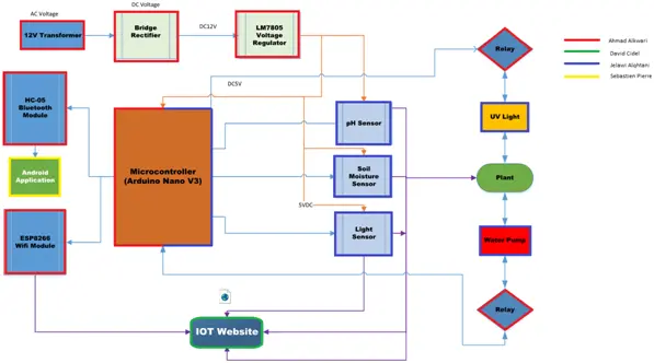
5. Hardware block diagram
Figure 2, labeled “Hardware Block Diagram,” illustrates the hardware configuration.
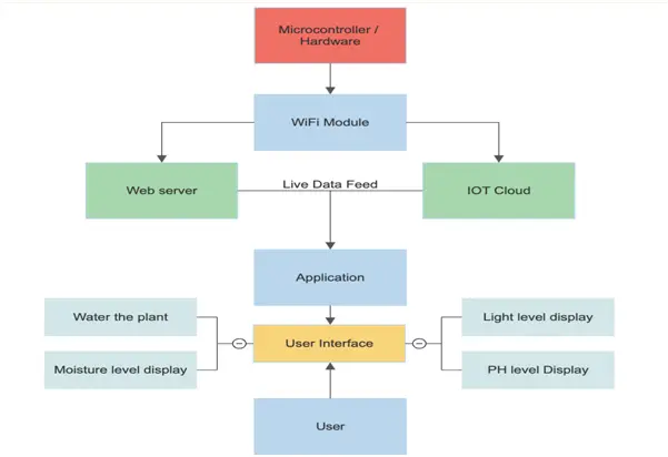
6. Software block diagram
Figure 3, titled “Software Block Diagram,” illustrates the structure of the software components.
7. Estimated Project Budgeting
In a nutshell, without factoring in unforeseen expenses or the necessity to reacquire certain items, the anticipated initial budget for this project falls within the range of $150.08 to $487.17. When the budget is distributed among the four project members, the estimated cost per participant to complete the project is roughly in the range of $37.52 to $121.79, as detailed in Table 2, labeled “Estimated Project Budgeting.”
Table 2 “Estimated Project Budgeting”
| Device/Part | Approximate Price |
| SENSORS: | |
| Soil Moisture Sensor | $7.00-$40.00 |
| Temp/Humidity Sensor (DHT11) | $1.50-$7.00 |
| Light Sensor (LDR) | $6.00-$20.00 |
| PH Sensor | $6.00-$30.00 |
| Electronics: | |
| CPU | $10.00-$40.00 |
| Microcontroller | $1.00-$15.00 |
| Bluetooth module(HC-05) | $2.00-$20.00 |
| Development Kit | $30.00-$50.00 |
| Wifi Module(ESP8266) | $2.00-$15.00 |
| Circuit Elements: | |
| Diode(1N5408) | $0.72-$2.12 |
| Diode(1N4007) | $0.06-$1.50 |
| Capacitor (25V) | $0.79-$2.00 |
| Voltage Reg(LM7805) | $0.50-$1.40 |
| Terminal Blocks | $0.99-$1.04 |
| Switch Transistor(BC547) | $0.92-$1.21 |
| Resistors | $0.60-$0.90 |
| PCB | $20.00-$60.00 |
| MISC: | |
| Batteries | $10.00-$20.00 |
| Container | $30.00-$50.00 |
| LED Lights | $20.00-$60.00 |
| Software Expenses | $0-$50.00 |
| Shipping Expenses | TBD |
| Approximate Total Price Range: | $150.08-$487.17 |
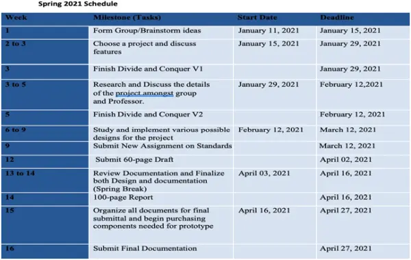
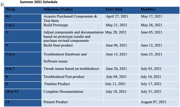
8. Initial Project Milestones
Table 3 “Initial Project Milestones”
9. Hardware Components
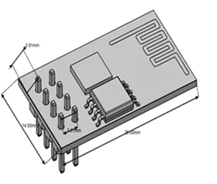
9.1. ESP8266 WIFI Module
– Voltage Supply: Operates at 3.3V
– Power Usage: Draws 100mA of current
– Input/Output Voltage: Handles up to 3.6V
– Input/Output Source Current: Supports up to 12mA
– Flash Memory Capacity: Equipped with 512KB of memory
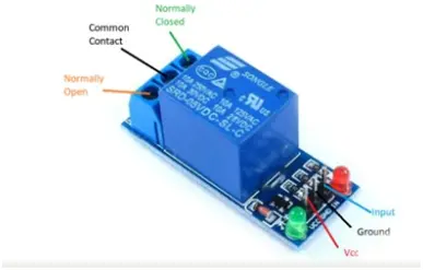
9.2. Single Channel 5V Relay Module
• Input voltage range: 3.75V to 6V
• Standby current: 2mA
• Current during relay activation: Approximately 70mA
• Maximum voltage for relay contacts: 250VAC or 30VDC
• Maximum current handling capacity of the relay: 10A
9.3. ULN2003 Module
• Features 7 Darlington pairs designed for high voltage and high current applications
• Each pair is rated at 50V and 500mA
• Input pins can be activated with a +5V signal
• The seven output pins can be linked together to drive loads of up to 3.5A (7 x 500mA)
• Directly controllable by logic devices such as Digital Gates, Arduino, PIC, and more
• Available in 16-pin DIP, TSSOP, and SOIC packages
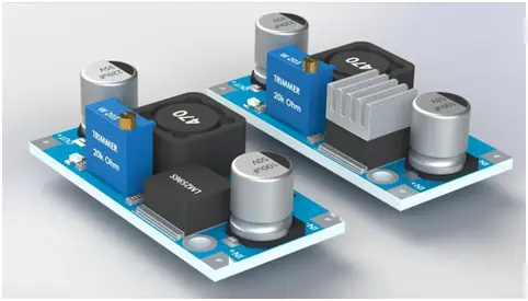
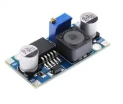
9.4. LM2596 Buck Converter Module
• Accepts input voltages within the range of 4V to 40V DC
• Provides output voltages ranging from 1.25V to 35V DC
• Maintains a voltage difference between input and output of over 1.5V
• Maximum output current: 1A (without cooling), 2A (with passive cooling*), 3A (with active cooling*)
• Achieves a maximum conversion efficiency of 92%
• Operates at a switching frequency of 65kHz
• Produces an output ripple of less than 30mV
• Exhibits load regulation within ± 1%
• Designed for operation in a temperature range from -40°C to +85°C
• Dimensions: 43.3 x 21.0 x 13.5mm
9.5. HC-05 Bluetooth Module
– Voltage Input Range: 3.3-5V
– Current Consumption: 30mA
– Effective Range: 10 Meters
– Compatible Baud Rates: 9600, 19200, 38400, 57600, 115200
– Physical Dimensions (Length x Width x Height): 28mm x 15mm x 2.35mm
9.6. Soil Moisture Sensor
– Voltage Range for Operation: 3.3V to 5V
– Current Consumption during Operation: 15mA
– Digital Output Range: 0V to 5V
– Analog Output Range: 0V to 5V
– PCB Dimensions: 3.2cm x 1.4cm
9.7. pH Sensor
– Voltage Input: 5V
– Current Consumption: 5-10mA
– Operational Temperature Range: 10-50 degrees Celsius
– Probe Response Time: Less than 2 minutes
– Noise Level: Less than 0.5 mV
9.8. DHT11 Sensor
– Operational Voltage: 3.3-5V
– Measuring Range: 20-95% Relative Humidity; 0-50 Degrees Celsius
– Precision: 8-Bit for Temperature, 8-Bit for Humidity
– Interface Compatibility: 2.54 3-Pin Interface
9.9. LM7805 Voltage Regulator
– Polarity of Output: Positive
– Type of Output Voltage: Fixed
– Output Voltage Range: 4.75-5.25V
– Current Capacity: 1.5A
– Input Voltage Range: 7-25V
9.10. 1N5408 Diode
● Current Rating: 3 Amperes
● Voltage Drop: 1.2 Volts
● Temperature Operating Range: -65 to 150 degrees Celsius
● Pin Count: 2
9.11. 1N4007 Diode
– Current in Forward Direction: 1A
– Voltage in Forward Direction: 1.1V
– Range of Operating Temperatures: -65°C to 150°C
– Number of Pins: 2
10. Alternative Projects Considered
10.1. Delivery Alert System
A device will be responsible for monitoring the vicinity of the front door and notifying the homeowner when a package is delivered. With the growing trend of online shopping and package deliveries, there is an increasing need to address concerns related to perishable items, potential attraction to animals, and the rising number of thefts.
This device will incorporate a scanning mechanism similar to a garage door safety system, featuring one or more mirrors strategically positioned to effectively cover the front porch area where packages are typically left. The system will be equipped with a timer to ascertain when an object has been delivered and subsequently alert the homeowner. Depending on its configuration, it may function independently using battery power and transmit wireless alerts. Alternatively, it might also be capable of generating text or audio messages if it has access to a telephone connection.
10.2. Hazardous Stove Mitigation
The intended purpose of this device is to automatically reduce the temperature of a stove heating element that has been inadvertently left on the “high” setting and subsequently forgotten.
The design of this device entails creating an add-on component that can be integrated into the heating element circuit, positioned between the existing controls and the electric burner. It will employ a combination of time-based and heat-sensing mechanisms to identify when a burner has been left on “high” for an extended duration, causing it to become excessively hot. This situation often occurs when there is no pot on the burner, or the pot’s contents have evaporated. The temperature can reach a dangerous level, potentially resulting in pot damage or the ignition of its contents.
In the event of an unsafe condition, the device will restrict the electrical current, effectively reducing the heat output of the burner. This feature is particularly valuable for households with senior residents living independently but can benefit most households.
A similar adaptation of this device could be developed for gas stoves; however, it would necessitate an external power source and gas-tight control mechanisms.
10.3. 360 Degree Car Surveillance
The concept here aims to safeguard the vehicle from collisions on all fronts. The approach involves strategically placing cameras to offer a complete 360-degree surveillance capability. When an object enters the detection range and seems to be approaching the vehicle, it triggers a warning or alert. This notification is intended to prompt the driver or owner to take preemptive action to prevent potential damage.
10.4. Automatic Plant Caretaker
An innovative plant care system designed for extended periods of unattended care. Instead of depending on a static system that provides a consistent but low level of watering, this system incorporates a moisture sensor to gauge soil moisture levels and deliver the precise amount of water required. The watering schedule can also be intelligently managed based on time and light levels, ensuring optimal hydration. Furthermore, the system could be augmented with additional sensors to monitor temperature and humidity, potentially integrating a misting system and even a pot rotation mechanism.
While primarily intended for use when the homeowner is away, this system can also serve for routine plant maintenance.
10.5. Facial Recognition Security System
A secure entrance would implement facial recognition technology for granting access to authorized individuals. The entrance would be equipped with a camera and a database containing images of authorized personnel. Upon reaching the entrance, individuals would position themselves in front of the camera for scanning. Subsequently, the system would analyze essential facial features within the image to verify the person’s authorization. If the analysis confirms authorization, the entrance would be automatically unlocked.
10.6. Parking lot management
Develop a system akin to Sunpass or EZpass, which organizations like UCF could employ to streamline parking management within their parking lots and garages.
Instead of traditional stickers, each parking permit would be an individual transponder, storing driver and vehicle information. When a driver enters the parking facility, they would receive a text message guiding them to a designated parking spot within a set time frame, typically around 5 minutes. If the driver fails to park in the assigned spot within this timeframe, the system would reassign the spot to another user. If someone parks in an area not allocated to them by the network, they would receive a violation ticket.
This system would enhance convenience for drivers by providing them with real-time information on available parking spaces. Simultaneously, it would enable UCF to cut costs by eliminating the need for manual parking lot patrols. Moreover, the transponders could be electronically updated to extend parking dates, obviating the necessity of issuing new parking permits, thus conserving resources.
10.7. Remote entrance security system
While many apartments and large office buildings commonly employ a network of wired doorbells, intercoms, and electronically controlled door locks, we propose the development of a wireless system utilizing WiFi.
In today’s digital age, almost everyone possesses a smartphone. In this wireless system, when a visitor rings the doorbell at the entrance, it triggers a notification to the resident by sending a text message containing a QR code image. To grant access to the visitor, the resident can forward the generated QR code image to the visitor. The visitor, in turn, would present this image to a scanner on the doorbell, which would read the code and confirm its match with the originally generated QR code, subsequently unlocking the entrance door.
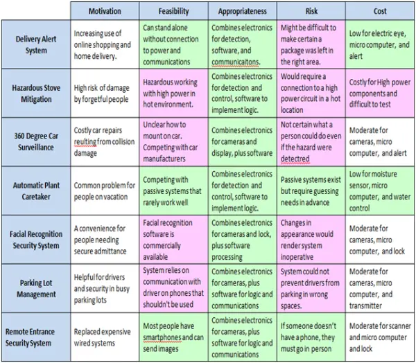
The following table offers a summary of the project ideas, with green indicating positive aspects and red indicating negatives. After evaluating these factors, we selected the automatic plant caretaker project as it had the most positive aspects and the fewest drawbacks.
11. Hardware Component Evaluation
11.1. Microcontroller
The project’s central processing unit is represented by the Microcontroller, serving as the project’s core control unit. It manages all project components, with its primary function being to receive, process information, and generate the desired output. The Microcontroller possesses built-in input/output (I/O) capabilities, enabling it to handle both analog and digital data by reading, processing, and writing such data. This device operates efficiently with minimal power requirements and stores its programs in EPROM, a non-volatile memory.
The selected Microcontroller for this project must be capable of receiving data from various sources, including the Wi-Fi Module and the Bluetooth Module, which interface with components such as the UV lamp, pump, Light Dependent Resistor (LDR), and pH sensor. Furthermore, the Microcontroller, based on information from the pH sensor, should be able to transmit high-frequency Pulse Width Modulation (PWM) signals to control the pump’s speed and the UV lamp’s brightness and intensity. This control mechanism creates the optimal environment for indoor plant growth.
Each project component, in conjunction with the Microcontroller, functions as part of a feedback control system, collectively regulating the indoor plant growth environment. To meet all these requirements, we need a cost-effective Microcontroller with an ample number of digital and analog pins, a high processing speed, and the ability to produce the desired outputs while staying within budget constraints. Two Microcontroller options considered for this project are the ATMEL ATmega328 and the ATmega168.
The Microcontroller is employed in various circuits, each serving distinct digital and non-digital purposes. These circuits utilize different bus systems to carry out their functions. These bus systems are structured to handle diverse tasks within the circuits. The digital and non-digital elements are arranged in arrayed form to execute the system’s various functions. The system is designed with different parallel bus systems, and digital systems like Read-Only Memory (ROM) in the PC are utilized to control the bus systems, facilitating data transfer and proper system functionality.
The illustration below provides a visual representation of this configuration.
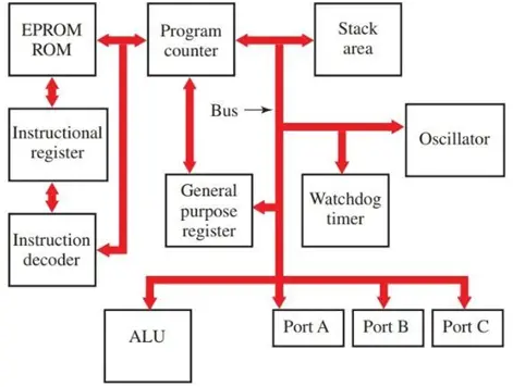
This system incorporates various bus systems that interact with the PC’s Read-Only Memory (ROM). These buses facilitate the transfer of instructions from the Instructional Register to the ROM processor, moving on to the programmer and, eventually, a General-Purpose Register. Additionally, ports A, B, and C are connected to an Arithmetic Logic Unit (ALU) as part of the digital system, forming an intricate network to process instructions.
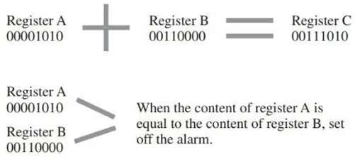
These components operate both in parallel and sequentially, with specific pins serving as inputs and outputs. The direction of these pins, whether set to input or output, significantly impacts their functionality. To achieve successful digital processing, the pin direction must be aligned with its intended purpose.
For instance, when manipulating mathematical data, the direction plays a crucial role in the outcome. The illustration below exemplifies how the result can vary based on the alignment of the analog signal. Alarm settings also depend on the equality of Register A to Register B, with different outcomes if they are not equal. When comparing Register A to Register B and Register B to Register C, if they are equal, the alarm settings will be closed.
11.1.1. Program Counter and Stack pointer
The stack pointer, a specialized device, plays a crucial role in managing the sequencing of tasks within the processor. It ensures that after one task is completed, the processor seamlessly transitions to the next, preventing any unwanted interruptions. In the event of an interruption, the system comes to a halt, leading to disruptions.
The entire system is intricately designed to execute various tasks smoothly, ensuring precise and efficient operation. When the processor is idle, it issues commands for the execution of other functions. All these functions work together, yet each has a distinct role in preventing disruptions.
Much like the stack pointer provides guidance, the program counter operates in a similar manner to ensure tasks are performed as intended. This synchronization is illustrated in the diagram below.
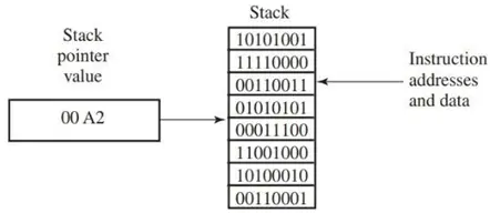
The stack pointer plays a crucial role in managing memory locations within a sequence, often referred to as a stack. It is responsible for handling data manipulation and processing various interruptions. Interruptions come in two primary types: Hardware and software interruptions.
Hardware interruptions involve the use of three input numbers to receive signals triggered by actions like pressing a button. These signals are detected by components other than the microprocessor. The stack pointer always points to the most recent position when the processor completes servicing an interrupt. It retrieves the counter address and resumes the counter program. The sequence of instructions provided by the microprocessor is followed as it directs the program counter and stack pointer, ensuring proper execution of tasks.
The program counter and stack pointer operate in a manner aligned with the required workflow, guaranteeing that processing proceeds in the intended direction. This synchronization allows hardware and software components to function as intended, responding appropriately to instructions from the interrupt handler.
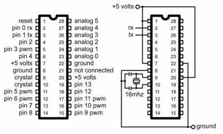
11.1.2. ATMEL ATmega328
The ATMEL ATmega328 is a commonly chosen 8-bit Microcontroller due to its ease of programming and widespread use in a variety of projects. It is favored for its user-friendly interface, featuring a 28-pin chip with an operational voltage range between 1.8V and 5.5V. This Microcontroller boasts 2KB of SRAM and 32KB of flash memory, offering ample storage capacity. It is equipped with 13 digital input/output (I/O) pins, 6 analog I/O pins, and 1KB of Electrically Erasable Programmable Read-Only Memory (EEPROM). The EEPROM functionality enables data storage and can provide results even after a power outage when electrical power is restored.
The ATMEL ATmega328 is compatible with Arduino and operates with a 16MHz crystal oscillator. On AliExpress, a package containing 10 pieces of ATmega328 is available for approximately US $16.80. This Microcontroller can be conveniently programmed using the Arduino Integrated Development Environment (IDE).
The ATMega-328 comes with detailed specifications that explain its functionality and purposes. These specifications provide valuable information about how and why this Microcontroller is utilized.
● Specially designed for high-performance applications, this 8-bit microchip serves as the main component.
● It boasts 32 flash memory for efficient read-write operations, effectively controlling the entire system.
● Featuring a 1KB EEPROM and 2KB SRAM microsystem, it ensures top-quality performance.
● With compare mode and three additional flexible modes (compare mode, external mode, and internal interrupted mode), it offers versatile operation.
● The device operates within a voltage range of 1.8 to 5.5 volts.
● The serial interface employs a two-wire SPI serial port, with options for 8-channel QF packages and TQFP, as well as 6-channel converters with 10-bit resolution.
● These robust chips exert precise control over the entire system, optimizing performance.
● Moreover, they strike a balance between processing speed and power consumption, achieving equilibrium. They execute strong instructions within a single clock cycle and approach MIPS per MHz.
The microchip’s processor demonstrates remarkable performance, despite its compact size. Its exceptional performance capabilities enable it to efficiently handle all functions within the system. This microchip is equipped with 32 flash memory for seamless read and write operations. It consistently delivers high performance while effectively controlling the entire system. Notably, it boasts a robust processing speed and a well-balanced power distribution system. Furthermore, its multi-bit architecture enhances its capacity to execute tasks with exceptional quality and efficiency throughout the system. The integration of 32 flash memory modules for read and write functions ensures optimal performance and comprehensive system control. In summary, this microcontroller excels at executing diverse and purpose-driven tasks, producing exceptional and consistent performance across the system. The ATmega microchip’s performance is distinguished by its quality, enabling it to effectively process all tasks with superior specifications.
11.1.3. ATMEL ATmega168
The second option for a microcontroller is the ATmega168, an 8-bit microcontroller. It serves as the predecessor to the ATmega328 and boasts 16KB of flash memory, 1KB of SRAM, and 512 bytes of EEPROM. This microcontroller operates within a voltage range of 2.7 to 5.5V and is generally cost-effective, with individual unit prices typically ranging from $1.2 to $1.3. It is readily programmable using the Arduino Integrated Development Environment (IDE) and operates with a 16MHz Crystal oscillator.
The ATmega168 is an AVR microcontroller with an 8-bit architecture and a 32-pin interface. It utilizes different technologies, including Complementary Metal-Oxide-Semiconductor (CMOS) and Is technology. The programmer is equipped with 16K memory, enabling control over reading and writing chips used for various programming purposes.
The project operates within a broad temperature range of 1.8 to 5.5 volts, and this temperature range is vital, particularly in the context of an embedded system or similar automation projects. The structural module system integrated into this project plays a pivotal role and should not be overlooked. This system exhibits diverse capabilities, making it adaptable for various programming systems, and its utilization is highly efficient.
This structural module system encapsulates multiple functions within a single-chip system, effectively serving as the core of the entire operation. The following points outline the features and capabilities of this module system, highlighting how the chip seamlessly handles various functions in the given context.
This real application system employs multiple processors to execute tasks efficiently. It ensures operations are carried out effectively and with precision, addressing various scenarios as needed. The chip itself is an impressive system equipped with all the necessary components to facilitate robust performance. Moreover, its rugged casing provides protection, ensuring its durability and reliability.
11.1.4. ATMega Characteristics
– This microcontroller is an 8-bit device featuring a range of AVR controllers and is available in various package systems like TQFP, MLF, and PDIP. It boasts a 32-pin interface, with 28 pins located on each side of the module.
– The program memory has a capacity of approximately 16K, comprising Flash-based, EEPROM, and RAM systems with capacities of 512 and 1K, respectively. Furthermore, it has a remarkable data retention capability of up to 20 years.
– The ADC module is a 10-bit component integrated into the device, playing a crucial role in interfacing with sensors and offering a total of 8 channels for digital conversion. These conversions result in consistent pin outputs.
– The microcontroller supports various communication protocols, including I2C, SPI, and USART. Among these, the ATmega protocol stands out as one of the most reliable and widely used for interfacing with external devices.
– This microcontroller demonstrates exceptional efficiency and functionality, consistently delivering valuable performance. It contains all the necessary components and information required for digital system operations.
11.1.5. MSP430G2553
The third microcontroller option under consideration is the MSP430G2553, available at an approximate cost of $10. It operates at 16MHz, offers 16KB of flash memory, and requires a 5V input voltage. However, it necessitates more extensive coding compared to the Arduino for tasks such as LCD interfacing, analog input processing, and initial setup. It’s worth noting that the MSP430G2553 lacks support for Mac or Linux environments and has a limited RAM capacity of 0.5KB.
The MSP430G2553 boasts several key features, including compatibility with MCUs in PDIP14 or PDIP20 packages, such as MSP430G2xx1, MSP430G2xx2, MSP430G2xx3, and MSP430F2xx. It is well-suited for ultra-low-power debugging and includes a button and three LEDs for user interactions.
It’s worth mentioning that the same company, ATMEL, manufactures the ATmega162.
11.1.6. Microprocessor Comparison:
When examining the feature sets of different Microcontrollers as detailed in Table 4, it becomes evident that the ATmega328 Microcontroller is the optimal choice for this project. This selection is motivated by the fact that the MSP430G2554 Microcontroller possesses an excess of features that are unnecessary for this specific project. One key consideration is that there is no requirement in this project to generate analog outputs to any part of the board.
Furthermore, the ATmega328 boasts a higher processing speed, operating at 20MHz, which surpasses the processing speed of the MSP430G2553. Given that some crucial project components necessitate running at higher voltages, specifically 12V, the ATmega328 is the preferred option, as it can operate effectively at these elevated voltage levels.
In a comparison between the ATmega328 and the ATmega168 Microcontroller, the ATmega328 stands out with its superior processing speed. Additionally, it offers greater flash memory capacity (32KB), EEPROM (1KB), and SRAM (2KB) when juxtaposed with both the ATmega168 and the MSP430G2553 Microcontroller. This enhanced capacity equips it to outperform the other mentioned microcontrollers in terms of functionality.
Furthermore, considering the overall value, the cost of the ATmega328 remains reasonable, even though it is slightly higher than that of the ATmega168 Microcontroller.
Source: Indoor Plant Maintenance System