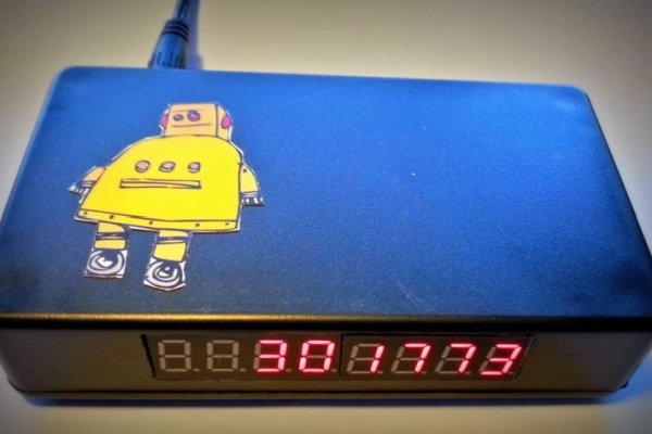
Some time ago, I tried to make an “Instructables Hit Counter” using the Instructables API, and an Arduino Uno with a wired network shield. However, with the limited RAM of the Arduino Uno, I was unable to get the system to work.
A while ago, I noticed a similar project done by diytronics using a NodeMCU. This was just the right kick-off point to redo my project.
Using the ESP8266-01 WiFi module, I studied the various options available, and redesigned the system.
The first problem when using the ESP8266 modules, is setting up the unit to connect to an existing WiFi access point. I did not want to do this using code, as this required the code to be changed and reprogrammed into the ESP8266. I found the WiFiManager library very useful, and made use of the examples to get the easiest method to connect the EP8266 to a WiFi network.
Next, I did not want to make changes to the code each time I wanted to change the Instructable to be monitored. For this, I set up the ESP8266 with a build-in web server to allow for easy changing of parameters.
Step 1: The Design
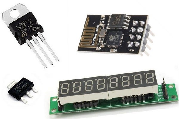
You will need the following components:
- 1 x ESP8266-01 Module
- 1 x max7219 8-digit 7 segment display
- 1 x 7805 Voltage regulator
- 1 x ASM1117 3.3V voltage regulator
Power Supply
The power for the unit is obtained from a 12V DC power supply. We will need two supplies:
- 5V for the max7219 display
- 3.3V for the ESP8266-01
Refer to the schematic diagram.
A diode is used to protect the unit from incorrect polarity connections, followed by the ON/OFF power switch. The input voltage is regulated to 5V by the 7805 voltage regulator. This 5V is used to power the max7219 display.
The 5V is also used to obtain the 3.3V needed by the ESP8266-01. The ASM1117 3.3 regulator is connected to the 5V regulator, and not to the DC input. This is to reduce heat that will be generated by the ASM1117 when connected to 12V supply. The ASM1117 3.3 used is a surface mount device, and can easily be soldered onto a piece of vero board.
AS the ESP8266 module can use up to 300mA when transmitting, each voltage rail is fitted with a decent sized smoothing capacitor. To eliminate HF noise, 0.1uf capacitors are also fitted to each voltage rail.
ESP8266-01
With limited I/O pins available, care should be taken to allow for the ESP8266 to boot up correctly. To get the ESP8266-01 module to boot up in the correct mode, the following must be done:
- CH_PD must be HIGH
- RST must be HIGH
- GPIO must be pulled HIGH
- GPIO2 must be pulled HIGH
This is done using 10K pull-up resistors. This will ensure correct boot-up of the ESP8266 module.
I/O Pins
My design needed 5 I/O pins for the following:
- 3 pins for the max7219 display
- 1 pin for the MODE/SETUP button
- 1 Pin for the buzzer
As the ESP8266 only have four I/O pins available, there is one I/O pin short. Therefor the buzzer and MODE/SETUP button is connected to a single I/O pin. Software will be used to control the INPUT/OUTPUT mode of this pin.
max7219 Display
The display needs three I/O pins, but with the ESP8266 only having 2 general purpose I/O pins, the Rx and TX pins will also be used. This means that no Serial Monitor is available during development. To control the display, GPIO1, Rx and TX pins are used.
Buzzer/Button
With only one I/O pin left (GPIO0), the buzzer and MODE/SETUP is connected to this pin, and by using multiplexing, the pin is used to read the button status as well as sound the buzzer.
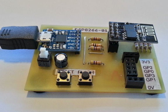
Step 2: Building the Circuit
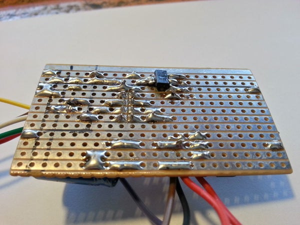
With only a few components needed, the circuit was build on a small piece of vero board. The SMD ASM1117 regulator was soldered to the track side of the board.
To connect the ESP8266-01, I used 2 x 4-pin headers. This allows for easy remove of the ESP8266 module for programming. A sharp hobby knife was used to separate the vero board tracks between the ESP8266 pins.
Wires for the display, buzzer and button were soldered directly onto the vero board.
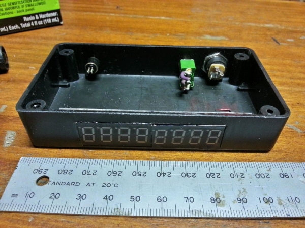
Step 3: Mounting the Display to the Enclosure
I had a small plastic enclosure available. To fit the display, I first make a cut-out for the display. The cut-out was made smaller than the display, and afterwards, filed to ensure the display fits snugly into the cut-out.
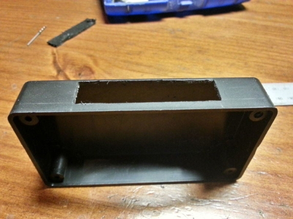
Using a permanent black marker, the white on the display was made black, and the display glued into position using epoxy.
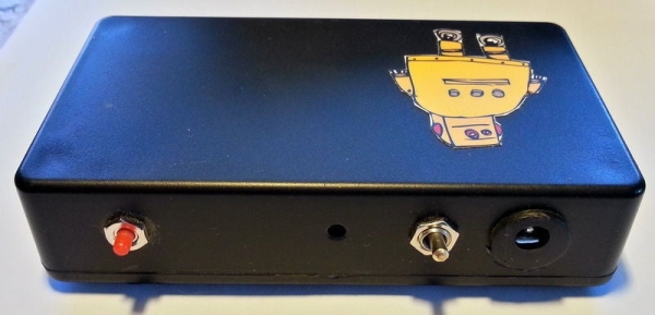
Step 4: Mounting Other Items
The power jack, On/Off switch, button and buzzer was mounted to the back of the enclosure.
For the buzzer, I drilled a 3mm hole in the enclosure, and glued the buzzer over this hole. This ensures that the buzzer will be load enough.
With all components fitted, the wiring between the components were made using thin wire.
Step 5: Programming the ESP8266-01
Upload the code to the ESP8266-01 with your method. For ease of reference, I have included the libraries used.
Please note that I have modified the LedControl library, thus you will have to use my LedControlESP8266 library.
Step 6: Connecting to Your WiFi
For the Hit Counter to function correct, we first need to connect the unit to a WiFi access point. Follow these steps:
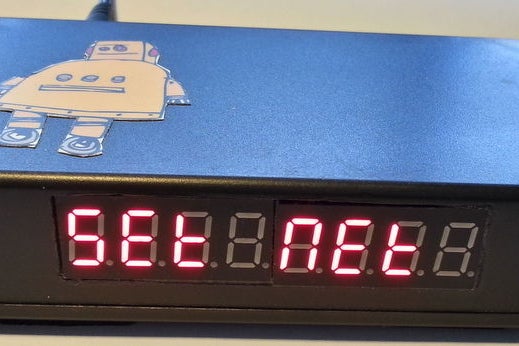
- Power up the unit
- When “Set Net” is displayed, press the MODE/SETUP button for about 2 seconds
- The display will now show “no con”
- Go to your PC or smartphone, and select the WiFi connections
- Select “Instructables Hit Counter”
- Open your internet browser. If the configuration page does not automatically open, type in the following IP address: 192.168.4.1
- Click on Configure WiFi
- Select the required WiFi access point, and enter the password for this access point
- Next, enter the IP address, Gateway and Mask as per your requirements
- Once done, click on the Save button
- When successful, you will receive a confirmation message that the data has been saved.
- Once connected, the Hit Counter will display the current configured hits
Step 7: Setup of the Hit Counter
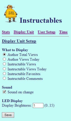
Once connected, the settings of the Hit Counter can be changed using the unit’s web page.
Open your web browser, and enter the IP address of the Hit Counter.
Hit Counters
The unit can be set up for two type of Hit Counters. Each of the counters have to be set up individually.
- Author Screen Name- Shows total number of hits for a specific author.
- Instructables ID – Shows total number of hits for a specific Instructable hits. Refer to the bottom of the web page for more information on obtaining the ID
Display
The unit can be set to display either the Author or Instructable hits:
- Select Author Total Hits to display total number of hits for the Author
- Select Instructbles ID Hits to display total number of hits for the Instructable
Sound
Select this option if you want the unit to beep on changes to the displayed hit counter.
Display Brightness
The display brightness can be changed via the web page. Enter a brightness level between 0 .. 15 as per requirements.
Step 8: Using the Instructabes Hit Counter
Once connected, the unit does not have a lot of functionalities. Apart from the MODE button, there is no other interfacing between the unit and the user.
Pressing the MODE button will alter the display between the Author Total Hits and Instructable Hits.
I hope you enjoyed this Instructable.
Regards
Eric
Source: Instructables Hit Counter (ESP8266-01)