Summary of Instrumentation Amplifier For Pressure Sensor
General-purpose differential amplifier for piezo-resistive pressure sensors that provides differential-to-single-ended conversion, gain, and a 0.75 V offset to produce a 0.75–4.75 V output compatible with microcontroller ADCs. The design uses an LM358 dual op amp in an instrumentation-amplifier configuration with trimmers for offset (PR2) and gain (PR1), supports MPXM2010GS and MPXV2010DP sensors, and includes dual supply or single-supply options using a 0-ohm resistor or short. Intended for amplifying small sensor outputs (25–50 mV full scale) for embedded ADC interfacing.
Parts used in the General purpose differential amplifier project:
- LM358 dual operational amplifier
- Resistors (multiple fixed resistors as per schematic)
- Capacitors (multiple capacitors including C8)
- PR1 trimmer potentiometer (gain adjustment)
- PR2 trimmer potentiometer (offset adjustment to 0.75 V)
- MPXM2010GS pressure sensor (footprint on PCB)
- MPXV2010DP pressure sensor (footprint on PCB; used for testing)
- 4-pin header connector for external sensors
- 0-ohm resistor (for single-supply configuration) or shorting link
- PCB with dual sensor footprints and associated wiring
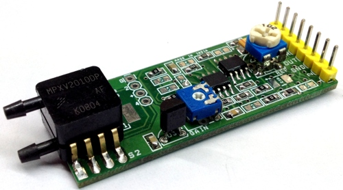
General purpose differential amplifier project has been designed for various pressure sensor amplifier applications. Circuit provided with multiple resistors, capacitors, dual sensor options and 4 pin Header connector to interface other external sensors. Schematic is an example from NXP application AN1318 Figure 2.
The most popular silicon pressure sensors are piezo-resistive bridges that produce a differential output.
Voltage output is in response to pressure applied to a thin silicon diaphragm. Output voltage for these sensors is generally 25 to 50 mV full scales. Interface to microcomputers, therefore, generally involves gaining up the relatively small output voltage, performing a differential to single ended conversion, and scaling the analog signal into a range appropriate for analog to digital conversion. The circuit published here is simple solution which amplify low voltage differential signal and provide single output voltage which can be directly feed to ADC of micro-controller. Instrumentation amplifiers are by far the most common interface circuits that are used with pressure sensors. An example of an inexpensive instrumentation amplifier based interface circuit uses an LM358 dual operational amplifier and several resistors that are configured as a classic instrumentation amplifier with one important exception. PR2 Trimmer potentiometer provided to set the offset voltage 0.75V. Setting the offset voltage to 0.75 V results in a 0.75 V to 4.75 V output that is directly compatible with microprocessor A/D inputs. Over a zero to 50° C temperature range, combined accuracy for an MPX2000 series sensor and this interface is on the order of ± 10%. Trimmer potentiometer PR1 helps to set the gain. PCB provided with MPXM2010GS and MPXV2010DP dual footprint options, for testing purpose MPXV2010DP sensors has been used.
The MPXV2010 series silicon Piezo-Resistive pressure sensors provide a very accurate and linear voltage output directly proportional to the applied pressure. These sensors house a single monolithic silicon die with the strain gauge and thin film resistor network integrated. The sensor is laser trimmed for precise span, offset calibration and temperature compensation.
Note : Board is designed for multiple applications and has dual supply input option, Use 0E resistor instead of C8 or short the two terminals since circuit works on single supply.
Read more: Instrumentation Amplifier For Pressure Sensor
- What is the purpose of this differential amplifier project?
To amplify small differential outputs from piezo-resistive pressure sensors, perform differential-to-single-ended conversion, and scale the signal for microcontroller ADC inputs. - Which op amp is used in the instrumentation amplifier configuration?
The design uses an LM358 dual operational amplifier. - How is the output offset set to be ADC compatible?
PR2 trimmer potentiometer is provided to set the offset voltage to 0.75 V, yielding a 0.75 V to 4.75 V output range. - How can the gain be adjusted?
PR1 trimmer potentiometer is used to set the gain. - Which pressure sensors are supported by the PCB?
The PCB has dual footprints supporting MPXM2010GS and MPXV2010DP sensors. - What output voltage range does the interface provide with the 0.75 V offset?
The output range is 0.75 V to 4.75 V. - What is the typical full-scale output of the silicon piezo-resistive sensors?
Output is generally 25 to 50 mV full scale. - Can the board operate on a single supply?
Yes; for single-supply operation, use a 0-ohm resistor instead of C8 or short the two terminals. - What accuracy can be expected with an MPX2000 series sensor and this interface?
Combined accuracy over 0 to 50°C is on the order of ±10%.