
Summary of Intel Edison Spectrophotometer
This article guides DIYbio enthusiasts in building a basic spectrophotometer using an Intel Edison and Grove components. It explains the fundamental principles of spectrophotometry, such as measuring light transmission through samples using prisms or gratings. The project connects a light sensor and LED to an expansion board to create a functional, albeit non-commercial, device for understanding wavelength analysis.
Parts used in the DIY Spectrophotometer:
- 1 x Intel Edison
- 1 x Grove Base Shield
- 1 x LED driver board
- 1 x LED (color LED used)
- 1 x Light Sensor
- 2 x Grove Cable
This instructable will explain how to build a fairly basic.
Of course, this device is nothing compared to a commercial spectrophotometer, but it will allow the builder to understand how such a device works to using it for DIYbio.
Know-how
The spectrophotometry is the quantitative measurement of the reflection or transmission properties of a material as a function of wavelength. Aspectrophotometer is commonly used for the measurement of transmittance or reflectance of solutions, transparent or opaque solids, such as polished glass, or gases.
The basic principle is easy: a beam of light passes through a prism or diffraction grating; out of the resulting spectrum, a range of wavelengths gets selected by sending the light through a slit. The light passes through the sample and hits a detector.
The most common spectrophotometers are used in the UV and visible regions of the spectrum, and some of these instruments also operate into the near-infraredregion as well. Visible region 400–700 nm spectrophotometry is used extensively in colorimetry science.
So, let’s do it!
This device is certainly not to be compared to a commercial system, but if you are a DIYbio fun it will certainly be interesting!
Step 1: Step 1: Materials
For this bit you’re going to need the following.
(I am using modules from the grove kit from seeedstudio)
- 1 x Intel Edison;
- 1 xGrove Base Shield;
- 1 x LED driver board;
- 1 x LED of your choice (I used a color led);
- 1 x Light Sensor;
- 2 x Grove Cable
Step 2: Step 2: Connecting it all together!
Before we get stuck in I am assuming you have your Edison board set up as in Intel guide; if not you can view it here.
Before connecting it all up, I suggest you disconnect the power from the board, it helps prevent any short circuits and other issues.
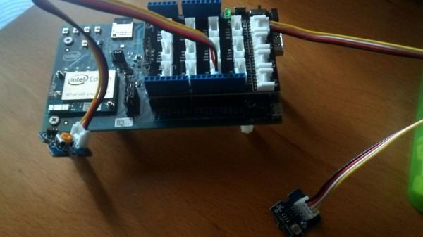
Firstly, you must connect the Grove Base Shield on Intel Edison Board.
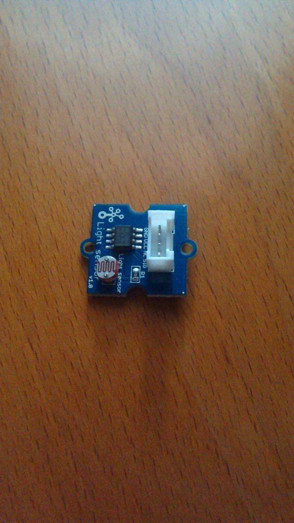
Then, the light sensor needs to connect to port A0 on the expansion board.
The Led Socket needs to connect to D3 on the expansion board with a LED.
Done, it’s all!
For more detail: Intel Edison Spectrophotometer
- What is spectrophotometry?
Spectrophotometry is the quantitative measurement of the reflection or transmission properties of a material as a function of wavelength. - How does the basic principle of a spectrophotometer work?
A beam of light passes through a prism or diffraction grating, selects a range of wavelengths via a slit, passes through a sample, and hits a detector. - Can this DIY device compare to a commercial spectrophotometer?
No, the article states this device is nothing compared to a commercial system but helps builders understand how such devices work. - Which region of the spectrum is visible region spectrophotometry used in?
The visible region is 400–700 nm and is used extensively in colorimetry science. - Where should the light sensor connect on the expansion board?
The light sensor needs to connect to port A0 on the expansion board. - Which port should the LED socket connect to on the expansion board?
The Led Socket needs to connect to D3 on the expansion board with a LED. - What safety step is suggested before connecting the components?
It is suggested to disconnect the power from the board to help prevent short circuits and other issues. - What type of kits are used for the modules in this project?
The project uses modules from the grove kit from seeedstudio.
