Detecting colour of an object can be an interesting and useful electronic application. It can be realized using a colour sensor like TCS3200 and a general purpose microcontroller like AVR ATmega32.
TCS3200 Colour Light to Frequency Converter Chip
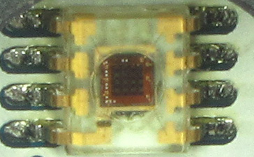
TCS3200 chip is designed to detect the colour of light incident on it. It has an array of photodiode (a matrix of 8×8, so a total 64 sensors). These photodiodes are covered with three type of filters. Sixteen sensor have RED filter over them thus can measure only the component of red in the incident light. Like wise other sixteen have GREEN filter and sixteen have BLUE filter. As you should know that any visible colour can be broken into three primary colours. So these three type of filtered sensors helps measure the weightage of each of primary colours in incident light. The rest 16 sensors have clear filter.
TCS3200 converts the intensity of incident radiation into frequency. The output waveform is a 50% duty cycle square wave. You can use the timer of a MCU to measure period of pulse and thus get the frequency.
The output of TCS3200 is available in single line. So you would ask how we get the intensity of RED,GREEN, BLUE and CLEAR channels? Well it has two inputs S2 and S3 that is used to select the sensor whose output need to be made available on the out line.
S2 | S3 | |
| RED | L | L |
| GREEN | H | H |
| BLUE | L | H |
| CLEAR | H | L |
So we select a channel either RED, GREEN, BLUE or CLEAR and then do the measurement of the output pulse width to get that channel’s intensity. In our library we have made these four functions to do this task.
 void TCSSelectRed()
 {
TCSS2Low();
 TCSS3Low();
 }
void TCSSelectGreen()
 {
TCSS2High();
 TCSS3High();
 }
 void TCSSelectBlue()
 { TCSS2Low();
 TCSS3High();
 }
void TCSSelectClear()
 {
 TCSS2High();
 TCSS3Low();
}
The functions TCSS2High(), TCSS2Low() etc are low level functions that controls the i/o lines connected to S2 and S3 lines.
TCS3200 Module
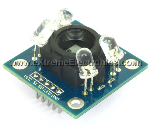
Since TCS3200 chip is a small SMD chip and is tough to prototype designs using the surface mount chip. Thus we have made a small module that has the TCS3200 chip, four white LEDs, LED control circuit and few other basic components on a PCB. The module has the connection all the line on 0.1inch male header. This makes it easy to connect with microcontroller boards. The white LEDs throws light on the object that is placed in front of the sensor. For best performance the object should be placed 1inch away from the LEDs such that the beam from all four LEDs converge at a single point (and do not make four distinct light spots on the object). One i/o pin of MCU can be used to switch on and off the LED.
In our library we have made two functions to control the TCS3200 module’s LEDs.
Fig. TCS3200 Module.
Measuring TCS3200’s Output
For measuring the output frequency of the TCS3200 we have used TIMER1 of AVR. Which is 16 bit timer. We have clocked the TIMER1 using same frequency as the CPU that is 16MHz without any division.
The function which is used to measure the frequency of TCS3200 is named TCSMeasure() The implementation of this function is given below.
For more detail: Interfacing TCS3200 Colour Sensor with AVR ATmega32


