Summary of Introduction to AVR Microcontroller Pulse Width Modulation (PWM)
This article explains Pulse Width Modulation (PWM) as an efficient method for controlling motor speed compared to analog techniques. It contrasts continuous current drive with PWM's on/off switching to reduce heat dissipation. The tutorial demonstrates generating PWM signals using an Atmel AVR Tiny2313 microcontroller, utilizing specific hardware boards and software tools for coding and programming.
Parts used in the AVR Microcontroller PWM Project:
- AVRJazz Tiny2313 learning board from ermicro
- JazzMate AVR-ISP STK200/300 programmer board from ermicro
- WinAVR for the GNU C compiler
- Atmel AVR Studio 4 for coding and debugging
- Kanda AVRISP STK200/300 programmer software
- LED connected to PORT B3
PWM is used in many industrial mostly for controlling the motor speed. The PWM is used because it’s the most efficient method comparing to the analog one. That’s why most of the modern microcontrollers today have this features build in. How does this PWM works will be described on the following circuits: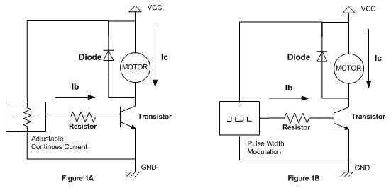
On the figure 1A the motor is controlled by applying continues current through transistor base lead and this will cause the continues current flow through transistor’s collector lead by the factor of transistor’s gain (Ic = gain x Ib); the more current we put on the transistor’s base lead the more current Ic will flow through the transistor’s collector lead; this also mean the motor speed is depend on the current we put on transistor’s base lead. Using this kind of method, make the transistor always in the working stage and as a result the power dissipation (power lost as heat) on the transistor become very high.
On the other circuit figure 1B the motor is controlled by applying pulse current through the transistor’s base lead and this will cause the Ic pulse current flow through transistor’s collector lead. By varying the pulse width and using the right frequency, we could control the motor speed. Using the pulse current make the transistor on and off very quickly, this will reduce much of the power dissipation on the transistor. This kind of method is known as pulse width modulation or PWM for short.
The disadvantage of using the PWM method is the electronics circuit to produce this signal tend to be complex, but thanks to today’s technology; even the most cheapest and tiny microcontroller such as AVR Tiny13 (only have 8 pins) could produce this PWM easily. For the purpose of this tutorial I will use Atmel AVR Tiny2313 microcontroller for playing with the PWM, but you could apply the principal to almost all AVR microcontroller family.
The following is the list of hardware and software I use in this tutorial:
- AVRJazz Tiny2313 learning board from ermicro
- JazzMate AVR-ISP STK200/300 programmer board from ermicro
- WinAVR for the GNU’s C compiler
- Atmel AVR Studio 4 for the coding, compiling and debugging environment
- Kanda AVRISP STK200/300 for the programmer software; nicely plug in to the Atmel AVR Studio 4.14
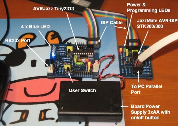
The AVRJazz Tiny2313 has four LEDs attached to the PORT B0 through PORT B3 and we will use the LED on PORT B3 for outputting the PWM signal. Ok let’s start the coding now !
For more detail: Introduction to AVR Microcontroller Pulse Width Modulation (PWM)
-
Why is PWM preferred over analog methods for motor control?
PWM is more efficient because it reduces power dissipation by switching the transistor on and off quickly rather than keeping it in a working stage. -
How does continuous current control affect motor speed?
The motor speed depends on the current applied to the transistor base lead, which causes continuous current flow through the collector lead. -
What is the main disadvantage of the PWM method?
The electronic circuit required to produce the PWM signal tends to be complex. -
Can small microcontrollers generate PWM signals?
Yes, even cheap and tiny microcontrollers like the AVR Tiny13 can produce PWM signals easily thanks to modern technology. -
Which microcontroller is used in this specific tutorial?
The tutorial uses the Atmel AVR Tiny2313 microcontroller to demonstrate PWM principles. -
Which port is used to output the PWM signal in this project?
The LED on PORT B3 is used for outputting the PWM signal.