Summary of LED Blinking with ATmega32 Microcontroller
Blinking an LED with an ATmega32 uses the microcontroller's default internal 1 MHz RC oscillator to toggle an LED at a 0.5 second rate. The guide shows the minimal circuit (no external crystal needed), a current-limiting resistor for the LED, required hardware and software, and a simple C program that sets PORTD as output and uses _delay_ms to create the blink timing.
Parts used in the Blinking LED with ATmega32:
- ATmega32A Microcontroller
- Power supply (5v)
- AVR-ISP Programmer
- 100uF Capacitor
- LED
- 220Ω Resistor
- Atmel Studio 6.1 (software)
- Progisp or Flash Magic (software)
Blinking LED is the first step you would like to take to get started with electronics. In this tutorial we are going to connect an LED with ATmega32, which is an AVR series microcontroller. We are going to blink the LED at half a second rate.
Components Required
Hardware:
ATmega32A Microcontroller
Power supply (5v)
AVR-ISP Programmer
100uF Capacitor
LED
220Ω Resistor
Software
Atmel studio 6.1
Progisp or flash magic
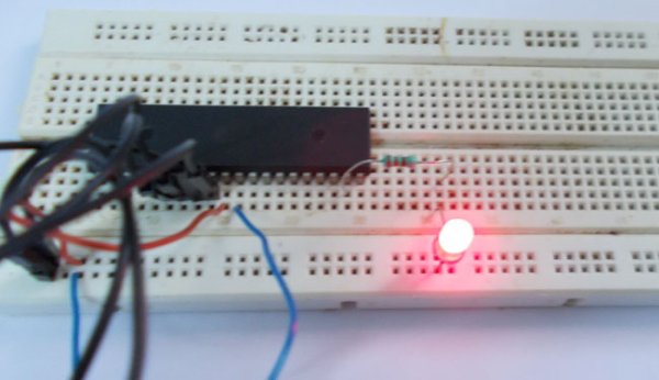
Circuit and Working Explanation
As shown in circuit, there is no need to connect an external crystal here. Because the ATMEGA works on internal 1MHz Resistor-Capacitor oscillator on default. Only when the accuracy of clock is needed, as application of high precision counting, external crystal is attaches. When the controller is first bought, it is fused to work on internal crystal by default.
The resistor is connected here to limit the current drawing from the LED. Remember, the controller can not provide more than 30mA at the terminals.
Programming Explanation
#include <avr/io.h> //header to enable data flow control over pins
#define F_CPU 1000000 //telling controller crystal frequency
#include <util/delay.h> //header to enable delay function in program
int main(void)
{
DDRD = 0xFF; // ( or 0b1111 1111) In AVRSTUDIO for telling the controlling to use a certain bit of a port as input we use “ZERO”, for telling it to use a certain bit as output we use “ONE”. Since we put eight “ONE’s”, all the pins of PORTD are enabled as output. If we put a zero as “0b1111 0111”, now all the pins 0,1,2,4,5,6,7 are enabled as inputs and PIN 3 is Enabled as input.
For more detail: LED Blinking with ATmega32 Microcontroller
- Do I need an external crystal to blink an LED with ATmega32?
No, the ATmega32 uses its internal 1 MHz RC oscillator by default so no external crystal is needed for this blink tutorial. - What limits the current to the LED?
A 220 ohm resistor is connected in series with the LED to limit the current. - What is the maximum current the controller can provide at a pin?
The article states the controller cannot provide more than 30 mA at the terminals. - Which port is used for the LED in the example code?
PORTD is configured as output (DDRD = 0xFF) so the pins of PORTD are used for the LED output. - How is the blink timing implemented in the code?
The code defines F_CPU as 1000000 and uses util delay functions (_delay_ms) to create the half-second blink rate. - Which software tools are recommended for programming the ATmega32?
Atmel Studio 6.1 is used for development and Progisp or Flash Magic is suggested for programming. - Is a capacitor required in the circuit?
The parts list includes a 100uF capacitor, implying it is used in the circuit. - How are port pins configured as input or output in AVR code?
In AVR code, writing a one to a DDR bit configures the pin as output and writing a zero configures it as input, as shown with DDRD = 0xFF enabling all PORTD pins as outputs.