
Summary of LM2596 DC-DC Converter Module Testing
### Summary The article analyzes a low-cost LM2596 step-down (buck) regulator module, questioning how it sells below the component cost. It details a reverse-engineered circuit featuring polarity protection diode D2 and notes that while the chip supports 45V input, capacitors limit safe operation to under 30V. The output voltage is adjustable via resistors R1 and R2 between 1.23V and 25V. Due to limited ground plane surface area, the board cannot dissipate heat effectively at high currents, necessitating a heatsink for continuous operation above 1A, with efficiency ranging from 60% to 90%.
Parts used in the LM2596 DC-DC Converter Module:
- LM2596 Step-down (buck) regulator
- Polarity protection diode (D2)
- Input capacitor (rated 35V)
- Output capacitor (rated 35V)
- Resistor R1
- Resistor R2
- Inductor (size varies by variant)
- Ground plane
According to TI’s website, these LM2596 step-down (buck) regulators are sold for $1.8 each for a quantity of a thousand. So how a finished converter could be sold for just above a dollar each is quite a mystery to me. Anyway, the picture below is the board I received. It appears that there are a few variations to this design (slightly different inductor size or capacitor size/voltage rating, etc.) but they all are largely based on the reference design.
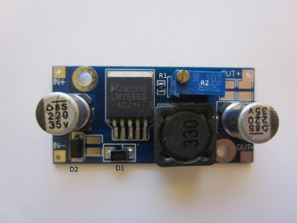
Below is the reverse engineered circuit diagram of this particular converter board I have (key components are also marked in the picture above for reference). The inclusion of a polarity protection diode (D2) is certainly a nice feature. It will prevent you from damaging the regulator should the input voltage be reversed. Of course, if the input power supply has very low output impedance and high current capability this tiny diode might not be able to save the board in an input voltage reversal situation. Also, not all variants of this step-down DC-DC converter have this diode. Although LM2596 can handle input voltages up to 45V, the input and output capacitors used are both rated for 35V only so in practice input voltage should stay below 30V for long term uses.
For LM2596, the output voltage is determined by the equation below. Given the component values used in this module the output voltage can be adjusted between 1.23V to 25V.
 23
23 R1R2+1
Although LM2596 is rated for a maximum current of 3A in continuous operation, the tiny surface area of the ground plane on this board is not sufficient to dissipate the amount of heat generated over the entire operation range of the converter. And the efficiency of this converter varies quite a bit depending on the input voltage, output voltage and the load current. The efficiency can range from 60% to 90% depending on the operating conditions. As you can see in the video later, a heatsink is a must if continuous operation at over 1A is required.
For more detail: LM2596 DC-DC Converter Module Testing
- How is the output voltage determined on this module?
The output voltage is determined by the equation Vo = 1.23 * (R1/R2 + 1), allowing adjustment between 1.23V and 25V. - Can I use an input voltage higher than 30V?
No, although the chip handles 45V, the capacitors are rated for 35V, so input voltage should stay below 30V for long-term use. - Does this converter have polarity protection?
Yes, this specific design includes a polarity protection diode (D2) to prevent damage from reversed input voltage. - Is a heatsink required for continuous operation?
Yes, a heatsink is a must if continuous operation over 1A is required due to insufficient ground plane surface area for heat dissipation. - What is the efficiency range of this converter?
The efficiency ranges from 60% to 90% depending on the input voltage, output voltage, and load current. - What is the maximum continuous current rating of the LM2596 chip?
The LM2596 chip itself is rated for a maximum current of 3A in continuous operation. - Are all variants of this converter identical?
No, there are variations such as slightly different inductor sizes or capacitor ratings, though they are largely based on the same reference design.
