
Summary of Load switch with self-resetting circuit breaker
### Summary This article describes a simple current-limiting load switch circuit using two transistors, Q1 and Q2, and a sensing resistor. It explains how negative feedback limits load current by comparing the voltage across the sensing resistor to the base-emitter voltage of Q1. The text details the calculation for maximum current based on VBE(on) and RCS values. It also highlights that while effective for low-power applications, the circuit dissipates significant heat in Q2 during short circuits, potentially requiring additional heat sinking for higher voltages or currents.
Parts used in the Load Switch with Self-Resetting Circuit Breaker:
- MOSFET Q2
- Transistor Q1
- Current-sensing resistor RCS
- Resistor R1
- Resistor R2
- Load
The simple current-limiting load switch shown in Figure 1 will be familiar to most readers. In this circuit, a high level signal applied to the input switches on MOSFET Q2, which energizes the load. The load current is limited by negative feedback applied via Q1.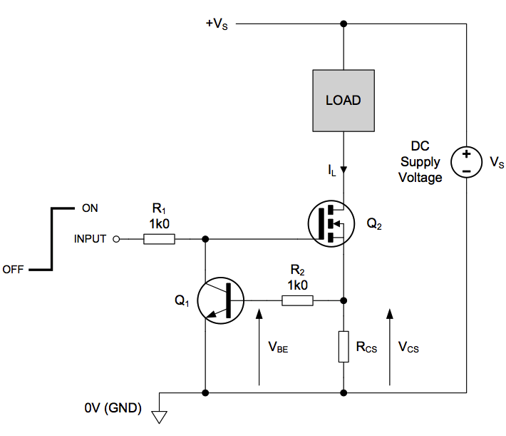
In most applications, the current flowing via R2 into Q1’s base will be very small compared to the load current IL, so the voltage VCS developed across current-sensing resistor RCS is roughly equal to Q1’s base-emitter voltage, VBE. Therefore, VBE ≈ VCS, and since VCS = ILRCS, it follows that VBE ≈ ILRCS, or IL ≈ VBE / RCS.
The value of RCS is chosen to limit the load current to a maximum value determined by IL(max) ≈ VBE(on) / RCS, where VBE(on) is the base-emitter voltage needed to bias Q1 into conduction. At room temperature, VBE(on) ≈ 650mV. So, for example, a value of RCS = 3.3Ω would set IL(max) to around 200mA.
Under normal, ‘no-fault’ conditions, where IL is within normal limits, VBE is too small to bias Q1 on, such that MOSFET Q2 remains fully enhanced by the high level signal applied to its gate via R1. Under these conditions, the load current is determined mainly by the load resistance and the supply voltage, VS. However, if a fault causes IL to approach IL(max), Q1 starts to conduct, and reduces Q2’s gate-source voltage to a level that holds the load current roughly constant, at a value given by IL(max) ≈ VBE(on) / RCS.
This linear current limiter is very effective for applications where IL(max) and the supply voltage are not too large. However, the circuit’s ability to limit the load current safely is determined by the power dissipated in Q2. For example, if RCS is selected to set IL(max) to 400mA and if VS = 12V, a short circuit across the load would dissipate almost 5W in Q2. Not only must Q2 be capable of handling this power with adequate margin, but additional heat-sinking may be required to keep its junction temperature at a safe level. Larger values of IL(max) and/or VS would simply exacerbate this problem.
For more detail: Load switch with self-resetting circuit breaker
- How is the load current limited in this circuit?
The load current is limited by negative feedback applied via Q1, which reduces Q2's gate-source voltage when the current approaches the maximum limit. - What formula determines the maximum load current IL(max)?
The maximum load current is calculated using the approximation IL(max) ≈ VBE(on) / RCS. - What is the typical value of VBE(on) at room temperature?
At room temperature, VBE(on) is approximately 650mV. - How does the circuit behave under normal no-fault conditions?
Under normal conditions, VBE is too small to bias Q1 on, allowing MOSFET Q2 to remain fully enhanced so the load current is determined by the supply voltage and load resistance. - What happens if a fault causes the load current to approach IL(max)?
If a fault occurs, Q1 starts to conduct, reducing Q2's gate-source voltage to hold the load current roughly constant at IL(max). - Why might additional heat sinking be required for this circuit?
Additional heat sinking may be required because the power dissipated in Q2 can become very high during a short circuit, depending on the supply voltage and current limit settings. - Does increasing the supply voltage affect the power dissipation in Q2?
Yes, larger values of supply voltage exacerbate the problem of power dissipation in Q2 during a short circuit.
