Summary of Make a 8×10 L.E.D Matrix using the Arduino and 4017 decade counter
This article guides readers in building an 8x10 LED matrix with scrolling text using an Arduino and a 4017 decade counter. It explains multiplexing techniques to save pins, offers two soldering methods for the grid, and details wiring options with or without a 74HC595 shift register to optimize pin usage.
Parts used in the 8x10 LED Matrix:
- Soldering iron
- Solder
- Small needle nose plier
- A wire striper
- 80 L.E.D.s (recommended 5mm diffused)
- 8 resistors (value depends on LEDs)
- 4017 decade counter
- 10 1KOhm resistors
- 10 2N3904 transistors
- Single core wire
- Perfboard
- Arduino
- 74HC595 shift register (optional)
- Pin headers (optional)
In this instructable I will show you how to build a quite fancy 8 by 10 L.E.D matrix(with scrolling text and animations) using the Arduino and 4017 decade counter. This type of matrix is easy to make and program and it is a good way learn how to multiplex.
I have added another part to this instructable about using the 74HC595 shift register which will help to save some arduino pins for other thing you would like to do.
So now you have to ways to go from here. You can make this matrix without the shift register and that will save you some soldering work or use the shift register if you want to have more free pins to use.
Stuff you need
Tools:
1. Soldering iron
2. Some solder
3. Small needle nose plier
4. A wire striper
For the matrix:
1. 80 L.E.D.s
2. 8 resistors( The value is determent by the type of L.E.D.s)
3. 4017 decade counter
4. 10 1KOhm resistors
5. 10 2N3904 transistors
6. Some single core wire
7. Perfboard
8. Arduino
optional –
9. 74HC595 shift register
10. some pin headers
Choosing L.E.Ds and resistors
This is one of the most important part of this project, because it based on LEDs it’s very critical to choose the right ones.
I recommend using 5mm diffused LEDs because they give a good amount of light and make a clear image(the color of the LEDs is your Choice only) .
You can use a 3mm LEDs too but it would make soldering really hard and you would get a small display.
Another tip is to buy the LEDs from Ebay because you can get a really good price and sometimes get free resistors as well (like in my case).
Do not buy exactly 80 LEDs because one or more of the LEDs can be damaged, my advice to buy 10 or 20 more, and if some will be left over you can always use them in future project.
Now to calculate the value of the 8 resistors you can use this site : http://led.linear1.org/1led.wiz.
You should first get some specs on your LEDs, you should know their forward voltage and forward current, you can get this info from the seller. The Arduino gives an output of 5V so your Source voltage is 5V.
Multi what?

So what is multiplexing:
It is basically a way to split information in to little peaces and send it one by one.
this way you can save a lot of pins on the Arduino and keep your program quite simple.
In our case we split the image that we want to display to 10 peaces (10 rows). We want to scan the rows of the matrix(light up one row at a time) and send info from the Arduino to the columns.
All the columns are positives of the LEDs and the rows are negatives so if the first row is connected to ground and we send information to the columns we will only light the first row.
To get a good display we need to scan the rows very fast. So fast the human eye thinks that all of the rows are connected at the same time.
So why the 4017:
For this LED matrix I wanted to use this useful IC.
Heres a good site to learn the basics of this IC : http://www.doctronics.co.uk/4017.htm
The 4017 decade counter is used to allow multiplexing.
This IC basically scans the rows of the matrix( lights up one row at a time).
In our case we want to connect the rows to ground but the 4017 doesn’t build to sink current, so to solve this little problem we need to use a transistor with a resistor.
The 4017 has 10 output pins so we need 10 resistors and 10 transistors, we connect the 1K resistors to the outputs of the 4017 and the base of the transistor to the other end of the resistor.
Then we connect the collectors of the transistor to the rows and the emitter to the ground.
Heres the data sheet of the transistor we need to use : http://www.fairchildsemi.com/ds/2N/2N3904.pdf
The shift register:
This little IC is a very useful one it allows you to control lots of outputs with the use of onlt 3 pins from the micro-controller. By connecting more IC’s you can increase the number of outputs with losing more micro-controller pins.
You can read more about them and how to use them with arduino in this link:
http://www.arduino.cc/en/Tutorial/ShiftOut
Soldering The Matrix
Soldering the LED matrix is a very tricky thing. There are a lot of ways to do it and I will give you just two.
The first one is the one I used and this way takes a lot of time and effort but the end result is very nice and pretty. You need to connect all the positive leads of the LEDs in columns and the negative lead in rows.
Now you do this by taking the positive lead of the first LED and bend it down to the other LEDs, solder the pins which touch each other, from here take the last lead that you soldered and bend it again down and repeat till you have all the positive leads connected in the column. snip the leads that you didn’t use.
The tricky part is connecting the negative pins in a row because you can’t bend them and solder like you did with the positive leads. Now I used little jumpers from solid core wire and connect them like you can see in the picture below( this takes lots of time and work).
The second way is to start the same way as in the first way but the only difference is in connecting the negative pins. This method saves lots of time and is a lot simpler.
The trick is to put some tape or another thing on the columns connections to isolate them from the negative pins and if you do that you can bend the negative leads too and connect them like you did with the positive ones.
Without the shift register:
Via a resistor you connect each column to the arduino(pins 0-7).
The reset pin of the 4017 goes to pin 8 on the arduino and the clock pin goes to pin 9 on the arduino.
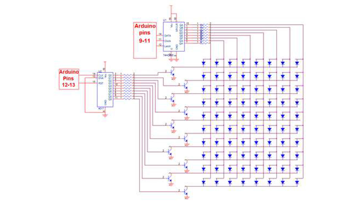
With the shift register:
Now if you connect every thing like shown in the schematic you will need to connect the control pins like so:
The shift register:
Data Pin = arduino pin9
Latch Pin = arduino pin 11
Clock Pin = arduino pin 10
The 4017:
clock pin = arduino pin 13
reset pin = arduino pin12
For more Detail: Make a 8×10 L.E.D Matrix using the Arduino and 4017 decade counter
- What is the recommended type of LED for this project?
The author recommends using 5mm diffused LEDs because they provide good light and a clear image. - How many extra LEDs should I buy?
You should buy 10 or 20 more than the required 80 to account for potential damage during assembly. - How do you calculate the resistor value for the LEDs?
You can use the site http://led.linear1.org/1led.wiz by inputting your LED specs and knowing the Arduino provides 5V. - Why is the 4017 decade counter used in this project?
The 4017 is used to allow multiplexing by scanning the rows of the matrix one at a time. - How are the transistors connected to the 4017 outputs?
Connect 1K resistors to the 4017 outputs and the transistor base, then connect the collectors to the rows and emitters to ground. - What are the benefits of using the 74HC595 shift register?
It allows control of many outputs using only three microcontroller pins, saving pins for other uses. - Which Arduino pins are used when not using the shift register?
Columns connect via resistors to pins 0-7, the reset pin goes to pin 8, and the clock pin goes to pin 9. - How does the second soldering method differ from the first?
The second method saves time by isolating column connections with tape so negative leads can be bent and soldered like positive ones. - Can you use 3mm LEDs for this matrix?
Yes, but it makes soldering very hard and results in a smaller display.