Summary of Make Your Own ‘Home Computer’
This article guides users in building a retro-style home computer using an Espruino Pico microcontroller. The project involves assembling four keypads on a base, wiring them to the Pico via a breadboard, and connecting an old VGA cable for display output. Users program the device using the Web IDE with custom code to emulate an 8/16-bit computer experience running JavaScript.
Parts used in the Home Computer Project:
- Espruino Pico
- Plastic or wood base
- Breadboard
- 4x 4x4 KeyPads
- Stickers
- 40x Male-to-Male Dupont-style Jumper wires
- Old VGA cable
- Solid core wire
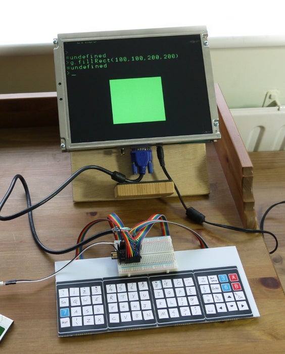
Many of us learnt to program on a Sinclair Spectrum, Commodore 64, BBC Micro or similar – 8/16 bit Home Computers. These computers booted straight up to a command prompt and encouraged you to write code and play with them.

You can now make your own (that runs JavaScript) in a few hours using a Espruino Pico microcontroller!
YOU’LL NEED
- An Espruino Pico
- A piece of plastic of wood to act as a base
- A Breadboard
- 4x 4×4 KeyPads
- Lots of Stickers
- 40x Male->Male Dupont-style Jumper wires – a multicoloured strip of them makes life a lot easier
- An old VGA cable
Step 1: The Keyboard

- Stick your 4 KeyPads next to each other on your base (they’re sticky-back). You may want to trim their edges down, but be careful not to trim too far or you might cut some contacts off.
- Stick your breadboard down in the middle – it’s sticky-back too!
- Split the jumper wire into 4 lengths of 8 – try and keep the colours the same on each.
- Stick the wires into the KeyPads, making sure the colours all match. Fold the wires back and tape them to the rear of your base. You might want to add some sticky feet to save the wires from getting bent at too much of an angle.
Step 2: Wiring
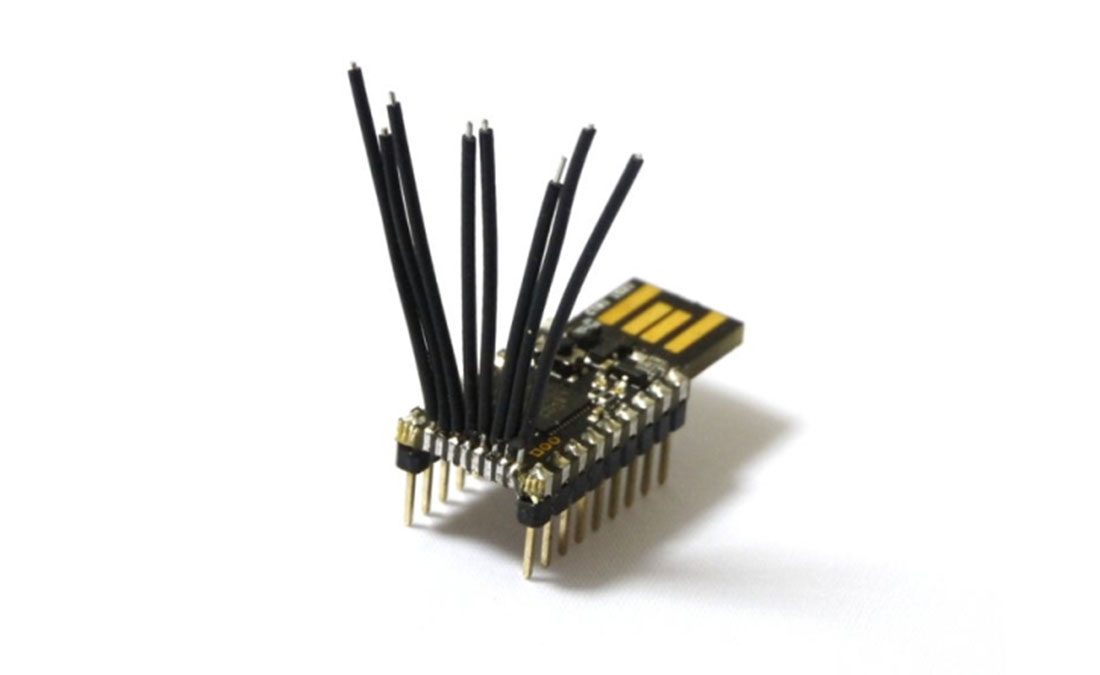
- Now you need the extra pins on your Espruino Pico. Get some solid core wire and solder it to the 0.05″ pins, checking none of them are shorted!
- Put the Pico into the left-hand side of the breadboard, strip and place the wires as in the picture above.
- Now you need to wire the keyboard. Do it as shown in the picture (check the colours of wires), with left to right:
- KeyPad 1 First 4 wires -> B6,B5,B4,B3
- KeyPad 1 Second 4 wires -> B9,B8,A8,B7
- KeyPad 2 First 4 wires -> B6,B5,B4,B3
- KeyPad 2 Second 4 wires -> A4,A3,A2,A1
- KeyPad 3 First 4 wires -> B10,B13,B14,B15
- KeyPad 3 Second 4 wires -> B9,B8,A8,B7
- KeyPad 4 First 4 wires -> B10,B13,B14,B15
- KeyPad 4 Second 4 wires -> A4,A3,A2,A1
Step 3: Wiring Up VGA

- Cut an old VGA cable in half and strip out the wires. The colours of the wires will be different, so use a multimeter to work out which wire goes to which pin on the VGA cable (they’re numbered in the diagram above).
- To make connecting easier, you may want to cut up some of the left-over dupont wires you used for the keyboard and twist/solder them onto the 4 wires from the VGA connector.
Step 4: Keyboard Keys

- Take the sticky labels and put them on all the keypad keys.
- Label each one the way you want the keyboard. It’ll be easier if you do it as in the picture above (as that’s what the software is for), but if you’re used to non-english keybaords and want to use different keys, go for it!
Step 5: Software
- Next, you need to program the Espruino Pico. Follow all the instructions at http://www.espruino.com/Quick+Start to get the Web IDE working and update the firmware to the latest version.
- Download the attached code file
- Then, in the Web IDE, click load and choose the code file. It should bring it around 100 lines of code.
- You’ll see pretty clearly there are two sets of strings that say things like QWERTYUIOP – these are the KEYMAPLOWER and KEYMAPUPPER variables. If you used a different layout for your keyboard, put the new characters in the right order in these.
- Click ‘Send to Espruino’
- When that is done type save() in the left-hand pane of the IDE. It’ll save the code to Espruino and your Home computer should start working!
Source: Make Your Own ‘Home Computer’
- How do I connect the keypads to the Espruino Pico?
Connect the first 4 wires of Keypad 1 to pins B6, B5, B4, B3; the second 4 wires to B9, B8, A8, B7; follow specific pin mappings for Keypads 2, 3, and 4 as detailed in Step 2. - Can I use a different keyboard layout than QWERTY?
Yes, you can edit the KEYMAPLOWER and KEYMAPUPPER variables in the software code to match your preferred non-English or custom key arrangement. - What is the best way to prepare the VGA cable for connection?
Cut an old VGA cable in half, strip the wires, use a multimeter to identify which wire goes to which numbered pin, and optionally solder twisted dupont wires to the connector for easier connection. - How do I save the code to the Espruino Pico?
After sending the code via the Web IDE, type save() in the left-hand pane to store the code permanently on the device. - Does the project require soldering?
Yes, you must solder solid core wire to the 0.05" pins on the Espruino Pico and may need to solder wires onto the VGA connector. - How many jumper wires are needed for this build?
You need 40 male-to-male Dupont-style jumper wires, preferably in a multicoloured strip to help distinguish connections. - Where can I find the instructions to set up the Web IDE?
Follow the instructions at http://www.espruino.com/Quick+Start to get the Web IDE working and update the firmware. - What acts as the base for the keyboard assembly?
A piece of plastic or wood serves as the base where the sticky-back keypads and breadboard are attached.