Summary of Making a LED Message Display with Keyboard Interface
This article describes a low-cost, AVR microcontroller-based LED signage system designed for scrolling messages in venues like offices and shops. Using an ATmega8 controller, the project drives four cascaded P10 displays with a 128x16 pixel resolution. It features a PS2 keyboard interface for direct message entry, which is stored in internal EEPROM to retain data without power. The design eliminates voltage regulators by utilizing a dedicated 5V SMPS, resulting in a compact and affordable solution for outdoor messaging needs.
Parts used in the LED Message Display:
- AVR ATmega8 microcontroller IC
- Four P10 LED display panels
- PS2 connector and standard keyboard
- Internal EEPROM
- 2x8 female header
- 2x8 male headers
- Power input terminal
- Output header for cascading
- 5V 6A SMPS power supply
LED signage has become the choice in modern days to convey message to visitors of a venue. Be it corporate office, shops, restaurants or any kind of social functions like marriages. Some big and complicated display needs dedicated control PCs and designers to build contents for them. But for simple requirements a very low cost AVR microcontroller based PCB is enough. This kind of display shows a message that scrolls from left to right on a LED display screen. To make it easy to use they don’t need any PC to program message to it. A PS2 keyboard can be attached and message can be typed. Message is stored in the internal EEPROM of the AVR and thus does not get erased even after the system is switched off.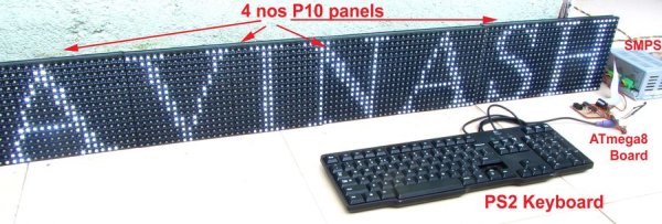
In this article we will discuss design of such a control board that can drive four P10 displays which has a combined resolution of 128×16 pixels and 4 feet length. Height is 6 inches. This is perfect for most outdoor display requirements. We have chosen AVR ATmegs8 which is a 28 PIN microcontroller IC. This IC is low cost and is available at under 90 rupees (US$1.50) Thus the control board is very low cost and small in size.
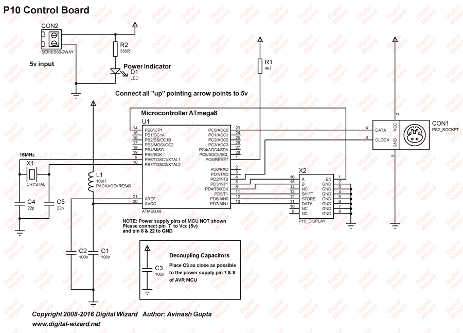
Circuit Design
Circuit design for moving message display is very simple. At the heart we have put the ATmega8 microcontroller, which is connected to a 2×8 female header that can be plugged directly to the 2×8 male headers for P10 display. Since P10 displays are cascadable, and has a output terminal too, this terminal can be used to connect next display. In the same way one more panel can be connected. So a total of four P10 panels are cascaded.
One more thing that is connected to the ATmega8 is a PS2 connector where we can hookup a standard keyboard. PS2 connector only has 4 connections.
We do NOT use any voltage regulator ICs in this circuit because to power p10 displays we need a 5v 6A SMPS power supply which already regulates voltage to 5v. So we can connect this 5v directly to the ATmega8 also.
As you can see in the image above the module has a 16 pin header that is used to connect it to the controller board. The board also has a power input terminal that should be given a 5v DC input that can source upto 3A current. The output header is used to connect more P10 panels to make a larger display.
For more detail: Making a LED Message Display with Keyboard Interface
- What is the primary purpose of this project?
To create a low-cost LED signage system that scrolls messages from left to right using a microcontroller. - How are the LED displays connected?
Four P10 displays are cascaded together using output terminals to achieve a combined resolution of 128x16 pixels. - Can users program the message without a PC?
Yes, a standard PS2 keyboard can be attached directly to type and store messages in the internal EEPROM. - Does the message stay saved after the power is turned off?
Yes, the message is stored in the internal EEPROM so it does not get erased when the system switches off. - Why are no voltage regulator ICs used in this circuit?
The 5V 6A SMPS power supply already regulates voltage to 5V, allowing direct connection to the microcontroller. - What is the maximum current required for the power input terminal?
The power input terminal requires a 5V DC input capable of sourcing up to 3A current. - What are the dimensions of the final display setup?
The setup uses four panels to create a display that is 4 feet in length and 6 inches in height. - Is the ATmega8 microcontroller considered expensive?
No, the ATmega8 is a low-cost IC available for under 90 rupees or US$1.50.