Introduction
For our final project in ECE 4760: Digital Systems Design Using Microcontrollers, we designed and implemented a radio-controlled, map-learning, line-following robot. The robot traverses a map of lines with a configuration that is initially unknown to a user. The robot discovers different types of intersections in the map and reports them to a base station, where the user can instruct the robot to discover new portions of the map. The two-way communication between the robot and the base station is achieved wirelessly through radio transceivers in the 2.4GHz frequency band. The base station consists of a PC application which displays the relative positions of the discovered nodes in the graph as well as the current position of the robot in real time. A user can direct the robot to explore new portions of the map or to return to a previously discovered node by clicking on the corresponding nodes in the map. The application takes care of finding the shortest path to the selected destination and automatically relays the necessary sequence of turns and movements to the robot.
High Level Design
In order to send wireless commands to the robot from our graph application (and back), we designed a five-node communication system. The application interfaces through UART with a base station module consisting of an ATmega1284p MCU. The base station translates the application commands into short packets and communicates with a Nordic Semiconductor nRF24L01+ radio transceiver via SPI to send the packets. The base station radio module communicates in the 2.4GHz frequency band with the robot’s own radio transceiver, which finally communicates with the robot’s ATmega1284p through SPI. Communication in the other direction is achieved in reverse.
We employed a back-and-forth protocol for communication between the application and the robot. After an initial handshake, the robot listens for commands from the application. Once a user tells the robot to discover the first node, the command to move forward and follow the line is sent to the robot. At the same time, the application switches to receiving and waits until the robot responds with the discovered node’s type. Similarly, commands from the application to the robot to execute turns are followed by a response from the robot as soon as the turn is successfully executed.
The line-following robot itself consists of two wheels in the front attached to continuous rotation servos which are driven at various speeds through pulse-width modulation (PWM) as well as a third, passive wheel in the back for support. The final iteration of the robot has a total of four infrared sensors capable of detecting their position, relative to the lines of the map. Two infrared sensors near the center of the robot are used for line following in conjunction with a proportional-differential control algorithm, and the remaining two infrared sensors on the sides are used for detecting nodes in the map and determining whether they are left turns, right turns, or branch nodes.
Hardware
Robot Chassis
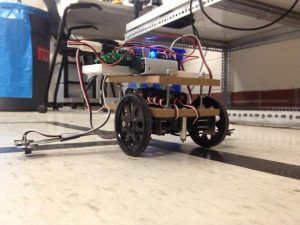
We designed a custom robot chassis to house all the necessary components for line-following, node detection and communication. The chassis is comprised of two tiers made out of wood, separated by four vertical bolts, with multiple nuts each, acting as standoffs. The bottom layer supports the servos with of custom mounting brackets and infrared sensors below. On the top side it has a velcro platform for the 6V battery pack used to supply power to the servos. The upper layer supports a 9V battery and the breadboarded robot circuitry, including the microcontroller PCB, the radio module, diagnostic LEDs, and plug-ins for the four infrared sensors and two servos.
Wheels and motors
The robot sits on top of three wheels, two in the front and one in the rear. The two front wheels are driven by Parallax Inc. continuous rotation servos, and are responsible for forward movement and turning. Turning is accomplished by using a differential in wheel speeds between the two front wheels. The speed and direction of wheel rotation is controlled by adjusting the width of the pulse received by the servos from the microcontroller. The third wheel is a freely rotating wheel, as to prevent any hindrance of the motion of the front wheels. Since the servo motors require a 6V to operate, we included a separate power supply consisting of 4 AA batteries to power them. The ground of the batteries was tied to the ground of the ATmega1284p, and the control signal of the servos was wired directly to the MCU.
Infrared sensors
For detecting lines, we used Parallax Inc. QTI(c) infrared sensors. A series of tests were conducted to determine the optimal layout for the infrared sensors on the underside of the robot chassis. After a few different iterations of sensor configuration, we ultimately decided on a design that utilized four sensors. Two inside sensors were positioned adjacent to each other directly above the line beneath the robot. These sensors are used for tracking and following the lines as the robot traversed the map. Two wings mounted on the underside of the chassis allowed the other two sensors to be placed a few inches to either side of the robot. These wing sensors are used for “node detection”, allowing the robot to be aware of when it arrived at an intersection, as well as which turns were possible to make upon arriving at the intersection. A further discussion of how the final configuration of sensors was decided upon can be found in the results section of this page.
Radio transceivers
Communication between the robot and the base station is done using a 2.4 GHz Nordic Radio Transceiver. The transceivers used are in a Sparkfun breakout package that steps down the 5V supplied to the chip to the necessary 3.3V used for operation of the transceiver. Both the robot and the base station communicate with their transceivers using an SPI port.
Base station
The base station circuit was assembled and soldered onto a perfboard. This circuit is comprised of the custom PCB with the microcontroller and auxiliary circuitry for operation of the microcontroller, as well as necessary hardware for SPI communication with the radio and UART communication with the PC hosting the Python control application. A Serial-to-USB wire connection with the host PC provides power to the base station and allows two-way data flow between the PC and the base station. This way, only one cable is needed to use the base station. If the application is running on a laptop, the base station becomes portable.
Software
Application
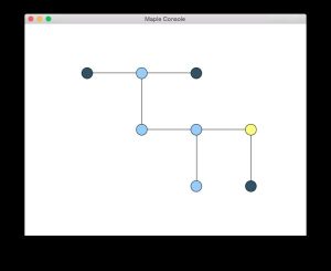
The host control application provides a GUI, giving the user control over the robot’s path and destination. The application was written in Python, using the PySerial library for communication with the base station, and NetworkX with matplotlib for graphical map generation and graph functionality, including A* shortest-path-detection. Clicking on a node on the map set the robot’s destination. Once a destination is selected, the path to that destination is decomposed into a list of single instructions to be sent to the robot. Each individual instruction is sent to the base station in turn, and the program waits for an acknowledgement of the instruction before continuing to the next instruction in the chain. When a destination is selected, the application determines the shortest path to that node from the robots current destination. The robot can also be instructed to visit unexplored nodes, resulting in a greater area of the map being exposed to the user. Previously-explored areas of the map are represented by light-blue nodes, and unexplored nodes are dark blue. The color of a given node becomes yellow while the robot resides at that node, and the robot’s destination is red while the robot is in transit.
Base Station
The base station software is in charge of relaying commands from the app to the robot and viceversa. The app commands to the robot are packaged into 1-byte payloads which are sent to the robot via the radio transceivers. Similarly, the 1-byte robot responses to the app are unpackaged by the base station into easy-to-understand strings. This made debugging communication much easier since packets to and from the robot could be easily read and understood by us. Also, by reducing the size of the payload, we sought to diminish the amount of dropped packets between the radio transceivers. Finally, since we found the radio communication between the base station and the robot to be unreliable, we built an application-layer acknowledgement system. Each packet that is sent between the robot and the base station is accompanied by an acknowledgement number, which is incremented after successful reception. This way, the base station transmits a packet repeatedly until it receives a response from the robot containing the acknowledgement number of that packet. The protocol for communication is described below:
App Commands to Base Station
2 characters:
| Command | Payload |
|---|---|
| GO STRAIGHT | go |
| TURN LEFT | tl |
| TURN RIGHT | tr |
| TURN AROUND | ta |
Base Station Commands to Robot
8 bits:
| Command | Payload |
|---|---|
| Unused | 0x00 |
| GO STRAIGHT | 0x01 |
| TURN LEFT | 0x02 |
| TURN RIGHT | 0x03 |
| TURN AROUND | 0x04 |
Robot Reports to Base Station
8 bits:
| Response | Payload |
|---|---|
| OK (response after turn or stop) | 0x0R, where R is the received command |
| BRANCH NODE | 0x20 |
| LEFT TURN NODE | 0x40 |
| RIGHT TURN NODE | 0x60 |
Base Station Responses to App
2 characters:
| Response | Payload |
|---|---|
| OK (response after turn or stop) | ok |
| BRANCH NODE | bn |
| LEFT TURN NODE | ln |
| RIGHT TURN NODE | rn |
Robot
PWM servo control
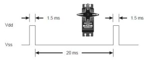
The robot’s continuous rotation servos are driven by a pulse-width modulation signal that determines the angular speed and direction of the wheels. The PWM pulse is delivered every 20 milliseconds. Although we initially generated the PWM signals manually using timer interrupts, the final version of our design makes use of the ATmega1284p’s fast-PWM mode on Timer 1 to drive the servos. We used Timer 1 rather than Timers 0 or 2 because Timer 2 is 16 bits wide, and we found we needed the higher resolution for accurate speed control and line following. Timer 1 is set to run at 62.5 kHz by applying a prescaler of 256. This way, by adjusting the lower byte of two output compare registers (OCR1AL and OCR1BL), the width of the PWM pulse to each motor can be varied in increments of 16 microseconds. The width of the pulse corresponding to the neutral point of the servos is 1.5 milliseconds. The servos were manually tuned to ensure this was the case. The maximum clockwise speed of the servos is achieved by delivering a 1.3 millisecond-wide pulse or less, while the maximum counterclockwise speed of the servos is achieved by delivering a 1.7 millisecond-wise pulse or more.
Line-following algorithm
In order to achieve reliable line following, we implemented a proportional- differential control algorithm that utilizes the ADC readings of the inner infrared sensors. A higher reading corresponds to a sensor being directly on top of the line, with the highest reading being closest to the center of the line, while a lower reading corresponds to a sensor being off the line or close to the edge of the line. The position of the robot relative to the line is able to be estimated by taking the difference between the two center sensor readings. In our control algorithm, we use an error term that corresponds to how far off the robot was from the center of the line, and a differential term that corresponds to the difference between the current error and the error of the last reading, providing an effective perpendicular velocity to the line. By taking a weighted sum of these two terms, we were able to adjust the speed of the left and right servos relative to their neutral points to correct the robot’s position towards the center of the line.
More information on our line following algorithm and how we arrived at it is detailed in the results section of this web page.
Node Detection
Detection of nodes in the map is achieved by taking digital readings of the outer wing sensors. Because the wing sensors are far away from the line, assuming the line-following algorithm is reliable we can determine when the robot lies at an intersection in the map by detecting when a wing sensor is on top of a line. If both wing sensors are on top of a line, the robot lies at a branch node. If only the right wing sensor is on top of the line, the robot lies at a right turn. Finally, if only the left wing sensor is on top of the line, the robot lies at a left turn. As soon as the robot detects a node, it slows down and advances forward for 50 milliseconds to ensure both wings are aligned with the center of the lines in the map grid. It then determines the type of node, reports it back to the base station, and awaits new instructions from the base station on what to do next.
Results
Line following
We tried multiple iterations of IR sensor configuration and line-following algorithms before arriving at the solution that was used in the final design. Our first design made use of digital readings from three sensors in a triangular configuration, with two sensors in the middle, and one “sniffer” sensor in the front. The middle sensors would straddle the line, and whenever the sensor transitioned from white to black, the wheel on that side would slow down. While following the line, the front sensor was to be kept above the black part of the line. Therefore, whenever the front sensor detected white, the robot knew it was at a node, and it would rotate in place to determine the node type. We found that this arrangement made node detection difficult because line following needed to be accurate enough to maintain the front sensor on the line at all times, which was hard to accomplish with only two sensors for line detection.
The second revision of the robot utilized four digital readings, adding wings to place two sensors on the outside of the robot for node detection. The advantage of this design over the previous one is twofold: line following no longer needs to be as accurate and determining the node type is easily accomplished without any rotation. As soon as either wing sensor detected a line, the robot knew that there were turns available, and that it must therefore be at a node. This configuration worked better than the previous one, but line following was still sporadic and inaccurate. The biggest pitfall of this design was that when the robot ended up completely off the line, which happened when the robot turned to correct its position too sharply, it would end up with both of the center IR sensors positioned off the line, on the same side. At this point, both sensors would detect white, which would be indistinguishable from straddling the line, so the robot would drift away from the line without correcting itself.
It was at this point that we decided that the center sensors used for line detecting should be located above the line, rather than straddling it. The logic being, if the sensors are looking to detect black in order to move forward, rather than white, there can be no false positives. The only information available when taking digital reads from two different sensors is whether the sensor is above the line or not. When using an algorithm which seeks to keep the sensors off the line, it becomes impossible to distinguish whether there is a sensor to each side of the line, or whether the sensors are both on the same side of the line. We tried a few different methods of keeping sensors above the line, including keeping the sensors on the edge of the line, and slowing down the opposite wheel when the sensor sees white, as well as a single sensor “scanning” algorithm, in which the robot would start with the sensor to the left of the line, and travel forward and to the right until the sensor saw the white to the right of the line, at which point it would switch the wheel’s rotational velocities and drift towards the left hand side of the line, and so on.
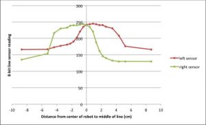
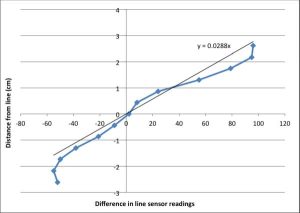
We found that these algorithms and sensor configurations were decidedly better and determining when the robot had gone off the line, but were still wildly out of control. The digital readings of the sensors were not providing enough resolution to implement accurate line following. We decided to run tests on the characteristics of the analog readings two middle sensors over the line. We took measurements of the output of the two sensors at different offsets from the middle of the line.
As illustrated above, the combination of sensor readings is unique for each offset of the robot, with a resolution of 0.5 cm in most locations. We took the difference of the sensor readings, and were able to achieve an almost linear correlation between sensor readings and lateral offset from the center of the line. This new finding allowed us to design an algorithm in which we adjust motor speeds based on a range of positional values, instead of a binary on-the-line/off-the-line value. Shown below is a chart of the robots offset vs the difference between sensor readings.
Proportional-differential control
Utilizing the analog sensor values from the two center QTIs allowed us to adjust the motor speeds with greater resolution. Originally we wrote an algorithm in which we adjusted the motor speeds linearly with offset, slowing down the motor on the side opposite the offset. We found that while this worked better than our previous digital-reading algorithm, we did not quite achieve the accuracy we were hoping for. We decided to try to implement a proportional-integral-derivative controller. We performed some value tuning and qualitative analysis of the robots ability to follow a long line (about 7 m). Our findings showed that the integral component of the PID control algorithm tended to correct too hard for the robot leaving the line, and would often result in it spinning in circles. This is most likely due to the fact that once the robot has left the line, all the distance information is lost as the difference between sensor readings becomes the same value regardless of where the robot is located. One surprising result from our tests was that the differential term of the PID control algorithm actually helped much more than the proportional term. After some analysis of this finding we arrived at the following conclusion: because the “error” value used in our control algorithm is distance away from the sensor, the differential term–the rate of change in this error–ends up being proportional to the robot’s velocity perpendicular to the line. Making the generalization that the robot moves at generally the same speed during travel means the robot’s perpendicular velocity can be effectively thought of as the angle of the robot’s trajectory with respect to the line. While following the path of the line, it is actually more important that the robot’s angle is corrected rather than its absolute position. We would rather keep the robot’s trajectory parallel with the line, at some small offset from the line’s center, than prioritizing being directly over the center of the line, causing the robot to turn at sharp angles displacing itself again and again, eventually becoming unstable and leaving the line. By experimenting with the coefficients for the proportional and differential terms, we found that a differential coefficient of 2.5 and a proportional coefficient of 0.08 resulted in reliable line following. As discussed, the differential coefficient was given a much higher weight than the proportional term (31 times greater). Although this results in some jerky motion at the edges of the line due to noise, it is successful in consistently keeping the robot on the line.
Communication
Getting reliable communication between the robot and the base station using the radio transceivers proved to be quite a difficult task. Initially, packets were regularly dropped, and would leave one of the two communicating parties hanging, indefinitely waiting for a response. Once a packet was lost, communication was unrecoverable until power was cycled on both devices. To increase reliability, we decided to add an application-layer acknowledgement system. When the host application sends a command to the robot, the base station continually relays this command to the robot until it receives a reply. We use sequence numbers for the packets, so that the base station is able to see what the robot is acknowledging. The base station retransmits packets until it receives an acknowledgement with a matching sequence number. For turns, this acknowledgement would come immediately. For travelling from one node to another, the base station would not receive an acknowledgement until the robot reached the node it was travelling to. After making this change, we found that at times the robot would not respond to base station commands. After reading a serial output from the robot, what we found was that sometimes the robot would never receive the first command from the base station, but if it had received the first command, it tended to receive the rest of the commands from the base station quite reliably. To account for this issue, we added a handshake instruction at initialization. While sending this instruction, the base station would repeatedly blink an LED to let the user know that it was in the process of pairing up with the robot. Upon successful retrieval of this instruction, the robot would turn on an LED to signify that it was properly connected to the base station, and proceed to send an acknowledgement. After receiving the acknowledgment, the base station would leave its LED on, signaling to the user that its ready to start sending instructions from the host control application to the robot.
Conclusions
In general, our system worked as expected. Though line following was more difficult to implement than we anticipated, ultimately the robot was able to reliably follow lines, report nodes in the map, and receive base station commands from the user to return to previously explored nodes. However, we did experience serious issues with achieving reliable wireless transmission between the robot and the base station, even after adding our own application- layer acknowledgment protocol. A large source of error may have been radio interference in the digital lab in Phillips Hall. Because the transceivers we used operate in the same frequency band as WiFi, the laptops and cellphones of students working in lab along with the lab’s concrete walls may have caused problems for reliable radio transmission. If we had time, we would have tried using different radio transceivers, using a different library, writing a new one from scratch, or abandoning radio altogether and switching to Bluetooth communication. We also would have liked to consider the distance between nodes in the map rather than assuming the map nodes lie on a square grid. Future work could also explore detection of nodes with more than four edges or reporting curved paths between nodes.
Intellectual property considerations
Our project made use of a modified version Yi Heng Lee’s library for the Nordic nRF24L01+ radio transceiver which was written for ECE 4760’s custom PCB board. Beyond that, we believe our design is original and free of intellectual property issues.
Ethical and design considerations
Our design, in its current state, is far from being marketable — there are many unenclosed wires and components which would make it unsafe for sale. A primary consideration would be the shortage of batteries due to exposed wires and the use of wood which can be a fire hazard in the presence of short circuits. Enclosing the robot and base station circuitry would be a step forward towards making our design safer to use. Since the robot is semi- autonomous, it would also be helpful to include a distance sensor at the front to prevent collisions with objects and people. This way, damage to the robot and its surroundings could be minimized.
Source: Maple Bot

