Summary of Master Microcontrollers with C Programming and the ATmega16
This article outlines the systematic development of embedded microcontroller software using C. It emphasizes reliability through rigorous coding, documentation, and testing. The process involves defining problems, creating algorithms, visualizing logic with flowcharts, and implementing code in C. Key components include preprocessor directives like `#include` and `#define`, the mandatory `main` function, and structured code blocks using curly braces. The guide uses the ATmega16 microcontroller as a primary example to illustrate these concepts for long-term autonomous operation.
Parts used in Embedded Microcontroller Software Development:
- C programming language
- ATmega16 microcontroller
- Header files (e.g., mega16.h)
- Preprocessor directives (#include, #define)
- Algorithms
- Flowcharts
- Simulators and emulators
- Real hardware
- Datasheets
- Interrupts and ASCII references
Embedded Microcontroller Software:
Embedded software presents a distinct challenge due to the critical need for reliability in continuously operating microcontroller systems. To ensure faultless long-term performance, best practices include thorough coding, documentation, and testing.
While not specifically designed for microcontrollers, the C programming language remains a popular choice due to its structured approach that compiles efficiently. Using a high-level language distances programmers from hardware intricacies. The compiler handles low-level details like memory allocation, allowing focus on functional logic apart from microcontroller specifics. This separation also enhances portability between platforms with modest effort.
However, microcontroller C variants contain unique attributes requiring experience to leverage fully. Unlike PC programs terminating to operating systems, embedded applications must run indefinitely without pausing. Program flow control remains an ever-present concern rather than a terminal concept. Effective embedded design centers continuous, autonomous operation within hardware constraints through disciplined software engineering employing language strengths for long lifetime embedded deployment.
Introduction:
Software development requires understanding the full problem-solving process before writing code. This site outlines the necessary steps: from initial problem definition through solution implementation.
It first covers fundamental problem-solving methodology. Algorithms are then developed to address problems logically, visualized via flowcharts. Flowcharts aid algorithm translation into working C programs.
C provides advantages for microcontrollers over assembly or other high-level languages. Its strengths suit microcontroller use well. Written software undergoes additional steps to load onto microcontrollers. Standards improve readability and maintainability during development.
Examples illustrate discussed topics. References support microcontroller software creation, including datasheets, interrupts, conversions, ASCII, hardware options, and programming.
Intended as a guided process, individual sections also function independently. Navigation lists topics in the intended sequence, from introduction through C programming conclusions.
References supplement required information without being formal lessons. Additional links direct to outside resources. This site leads students through the full development cycle to implement microcontroller solutions systematically.
Embedded Microcontroller Software:
Embedded software faces the singular challenge of reliably operating microcontroller systems continuously for years on end without fail. Achieving this necessitates rigorous coding practices, thorough documentation, and testing.
While not designed specifically for microcontrollers, C remains a staple due to enabling structured, efficient code generation from a high-level language. Its use decouples programmers from low-level hardware details handled by compilers. This allows focus on software logic independently of microcontroller specifics, enhancing portability between platforms with effort.
However, microcontroller variants of C contain unique attributes requiring mastery, even for experienced C programmers. Unlike PC programs terminating to an operating system, embedded applications must run indefinitely without pause. Flow control thus differs fundamentally from a terminal concept to perpetual management within hardware constraints. Effective embedded design centers continuous, autonomous operation through disciplined engineering leveraging C’s applicability for long-lived deployment.
Problem Solving:
Understanding and following a systematic problem-solving process is key to successful embedded application development. This site outlines the necessary steps.
First, fully comprehend the task by seeking clarification as needed. Without a clear goal, progress is difficult.
Next, devise a plan to solve the problem algorithmically before writing code. Algorithms must be tailored to hardware specifics researched through datasheets.
Flowcharts then translate algorithms visually and aid identifying repetitive tasks for modularization. This documentation benefits customers as well.
With preparation complete, coding can commence using C as the implementation language in this course. However, other languages are valid choices.
Testing and verification follow, using simulators, emulators, and real hardware. Iteration may revisit earlier steps to achieve desired outcomes, as software development is inherently iterative.
Breaking applications into manageable modules streamlines both development and testing. This modular approach, together with diligent problem-solving, facilitates creating robust embedded applications through a structured process.
Algorithms:
Algorithm development lies at the heart of successful software design. If a problem cannot be solved systematically on paper, programming it will likely fail. Computers and microcontrollers merely implement algorithmic solutions.
Some problems dictate a set processing order, while others tolerate flexible solutions. For example, adding numbers yields the same sum regardless of order, unlike temperature conversion between Fahrenheit and Celsius which requires a precise sequence.
This section defines algorithms and their role. An algorithm specifies unambiguous step-by-step instructions for solving a problem such that any user can achieve the same outcome. It provides sufficient detail and precision.
Key algorithm characteristics include:
Clear, precise steps leading uniquely to the solution
Use of only specified inputs/internally derived data
Defined starting point and termination conditions
Stated applicable input range(s)
Specified output(s)
When possible, generality to handle different data sets
Anyone following the algorithm should obtain identical results at each step and solve the given problem consistently. Algorithms abstract systematic solutions, independent of implementation method. They underpin programming by defining computations rigorously and unambiguously beforehand.
Flowcharting:
Flowcharts provide a graphical representation of algorithms using standardized symbols. Compacted to a single page for simplicity, the basic shapes represent:
Terminal (start/end points)
Process (actions/computations)
Decision (branch points)
Together with connecting flow lines and arrows, these visualize program logic and flow.
Structured flowcharts constrain programs to a single entry and exit point, aligning with structured programming principles. They aid translating algorithms into code, clarifying control structures introduced later.
Additionally, flowcharts serve as documentation. Experience reveals their usefulness elucidating others’ work.
Not limited to software, flowcharts diagram any process sequentially – such as the problem-solving methodology flowcharted below. Overall, flowcharts capture algorithms visually and convey understanding, whether for initial design, subsequent implementation, or documenting solutions thoroughly.
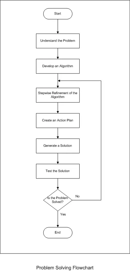
The initial problem-solving flowchart depicted generating a solution as a single block. In truth, developing a software implementation entails greater complexity. Processes simplify as single blocks.
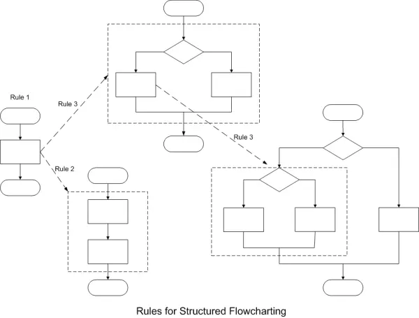
Structured flowcharting follows rules to capture intricate logic systematically:
Begin with the simplest representation.
Any process rectangle can expand to a series of steps.
Replace processes with control structures incorporating decisions and actions.
These rules may apply in any sequence and repeat iteratively. Below demonstrates refining the flowchart, splitting the generate solution block and introducing branching choices reflective of real-world problem-solving nuances:
Initial high-level view gives way to progressively richer detail while adhering to structured techniques. Flowcharts thus evolve to better model complications, providing increasingly informative documentation and design aids throughout software evolution. The structured approach facilitates comprehending even sophisticated algorithms through systematic refinement.
This updated flowchart further decomposes the “Generate a Solution” step from the previous Problem Solving overview. It applies the structured techniques discussed to provide richer detail.
The flowchart, titled “Software Development Process”, breaks the single block into a series of interconnected steps reflective of the real problem-solving journey. Decision points incorporate potential branching paths.
By systematically exploiting the rules for refinement, the flowchart progressively captures more complexity while maintaining coherence. It models the thought processes and iterations involved when tackling difficult challenges algorithmically.
This level of decomposition sheds new light on the solution generation phase. The structured approach facilitates comprehension of even sophisticated problem-solving methodologies through incremental improvement and documentation of interconnected logic.
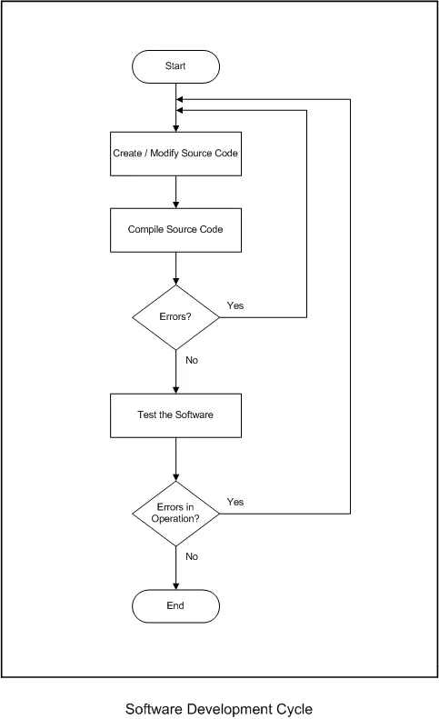
Both flowcharts depicted decisions that redirect flow if errors are detected in software operation or the overall solution. In this case, previous steps iterate to refine or rework them toward achieving desired results through testing and repetition.
While effectively demonstrating structured process documentation, the examples centered on problem-solving methodology and software engineering rather than “real world” microcontroller applications. Therefore, algorithms from the earlier section on algorithm development will now be revisited.
These algorithms model processes more representative of challenges routinely tackled using embedded systems. Focus shifts to examples readily implementable on microcontrollers through programming. The structured techniques shown apply equally there, aiding comprehension and documentation of even physical system behaviors and control flows through incremental refinement and interconnection of logical steps.
Revisiting more tangible embedded applications grounds the flowcharting methods in practical, “real world” programming scenarios. This enhances understanding of how systematic process documentation facilitates both initial design and ongoing management of microcontroller software projects.
Program Structure:
A basic embedded C program for the ATmega16 is shown below:
/*
Simple C program to illustrate the basic components of a program.
Written by: Jeffrey J. Richardson, Purdue University, February 18, 2003
This program actually performs no tasks, calls no functions, and uses no variables
*/
#include<mega16.h>
void main(void)
{
while(1); // stay here forever…never ending
}
Conventions dictate that most C code utilizes lowercase letters. A key property of C is that it is case-sensitive – the compiler distinguishes between capital and lowercase equivalents. Capitalization frequently designates constants defined with #define statements covered later.
Semicolons universally terminate all C statements. The language parser requires them to identify the end of each instruction. Their consistent inclusion allows programs to be written legibly across multiple lines in a structured manner understandable to both humans and machines. Semicolons unambiguously delineate statement boundaries.
Adhering to these syntactic norms aids readability and maintainability. Well-formatted code following expected patterns enhances comprehension and reduces defects. Case conventions separate constants from other identifiers while semicolons provide clarity through proper statement delineation. Together, they facilitate writing clean, standard-compliant C.
The Preprocessor Directives
C programs comprise statements and directives. Directives instruct the preprocessor, a program that executes compiler commands prior to compilation proper.
The most common preprocessor directives are #include and #define. #include tells the preprocessor to incorporate the entire contents of another file. Typically used with header files denoted by .h, these add microcontroller or library details.
Angle brackets < > indicate a standard include directory searched by the preprocessor. This default location is usually an INC folder alongside compiler files. Alternatively, double quotes ” ” specify the current directory as the start point. Directory and drive paths may then be provided as needed.
For example, the #include below uses double quotes to reference a header in the current working folder. Directives inform compilation by expanding includes and macros processing before code parsing. Well-placed directives streamline development through reusable declarations and macro-based abstraction.
#include “my_header_file.h”
define creates constants, values that never alter. Constants may specify maximum sizes or simply improve readability through more semantic names.
The preprocessor substitutes #define text with its succeeding definition throughout compilation. By convention, constants are CAPS for visibility.
For instance, MAX_SIZE utilized in code clearly communicates the variable’s role compared to a raw number. During preprocessing, it substitutes with the assigned value (100).
Constants defined via #define streamline code maintenance by centralizing literal values. Future changes only modify a single definition rather than searching/replacing every instance. Readers grasp usages intuitively from the descriptive names.
Overall, #define enhances comprehension, adapts programs flexibly to changing specifications, and prevents bugs from hard-coded magic numbers through abstraction and self-documentation.
#define MAX_SIZE 256
value = MAX_SIZE; // use a Constant to load the variable
In the above example, the line of code value = MAX_SIZE is transformer by the preprocessor to value = 256. The word or constant MAX_SIZE is replaced with the number 256. Constants can also be used in control statements. Control statements will be discussed in depth later, but the following example demonstrates the basic principle.
#define MAX_SIZE 256
if ( current_value > MAX_SIZE) // Test the value against a known maximum limit
{// code omitted for clarity
}
The Main( ) Function
All C programs incorporate at least one function – the primary entry point designated as main.
A function represents a discrete block of code providing a well-defined service. The main function differs subtly from others in that it executes automatically upon program launch without requiring an explicit call.
Functions will be explored in more depth later, but for now it’s important to note main occupies a special role as the initial task performed. As execution begins with main, it can be viewed as the foundational building block from which other functions either directly or indirectly stem.
Without main’s automatic invocation, no other code would run. It establishes the starting point and allows branching out to additional subroutines. For embedded applications, main typically oversees basic initialization prior to the ongoing core logic managed cooperatively by a assortment of supporting functions.
This hierarchical structure fosters modularity, reuse and maintenance – key virtues of well-engineered C programs built upon the foundations laid by the distinctive main entry point.
Code Blocks
Program structure signifies how code is organized, which impacts readability, debugging and maintenance. Structured programming techniques promote these virtues.
Code blocks delineate discrete logic units through enclosing curly braces {}. They form the building blocks of structured programs. Beginning and ending blocks establish scope for functions and control statements.
Consistent indentation, such as a single tab, visually distinguishes blocks from surrounding code for enhanced comprehension. This readability standard will apply here.
Curly braces may sit on their own lines to match block indentation levels, or remain inline. The compiler disregards whitespace and indentation, interpreting braces identically in either case. However, separating them aids human readers.
The goal is writing intelligible code. While inline braces can reduce page length for large programs, the author recommends consistent newlining for enhanced clarity. Structured organization and formatting streamline development through improved debugging and maintenance resulting from next programmers’ ease of understanding.
Overall, structured programming and standardized styling foster readability, a virtue that benefits projects throughout their lifespan.
void main(void)
{
while(1); // stay here forever…never ending
}
The above code is taken from the example program at the beginning of this section. Note that the braes are both indented and located on their own line of the code. This helps the programmer and anyone else reading the code recognize the presence of a block of code.
Source: Master Microcontrollers with C Programming and the ATmega16
-
Why is C preferred for microcontrollers?
C remains popular because it compiles efficiently, distances programmers from hardware intricacies, and enhances portability between platforms. -
How do embedded applications differ from PC programs regarding flow control?
Unlike PC programs that terminate to an operating system, embedded applications must run indefinitely without pausing or terminating. -
What is the first step in the problem-solving process for embedded development?
The first step is to fully comprehend the task by seeking clarification to ensure a clear goal exists before proceeding. -
How do flowcharts assist in algorithm translation?
Flowcharts provide a graphical representation using standardized symbols to visualize program logic and aid in translating algorithms into code. -
What are the key characteristics of a valid algorithm?
Key characteristics include clear precise steps, defined inputs, a starting point, termination conditions, and specified outputs. -
How does the #include directive function in C programs?
The #include directive instructs the preprocessor to incorporate the entire contents of another file, typically a header file, into the program. -
What is the role of the main function in a C program?
The main function serves as the primary entry point that executes automatically upon program launch to initiate all other code execution. -
Why are semicolons essential in C statements?
Semicolons universally terminate C statements, allowing the parser to identify the end of each instruction unambiguously.