Summary of Master the Art of Servo Motor Control Using AVR ATmega16
A servo motor article explains precise angular control via PWM, using an SG90 as example (0.52ms = -90°, 1.4ms = 0°, 2.4ms = +90°). It shows generating 50Hz PWM with ATmega16/32 Timer1 in Fast PWM mode (ICR1=2499, prescaler 64), mapping OCR1A values (65,175,300) to positions, and two example programs: fixed-position sweep and potentiometer-controlled mapping via ADC to vary OCR1A between 65–300.
Parts used in the Servo Motor with ATmega16/32:
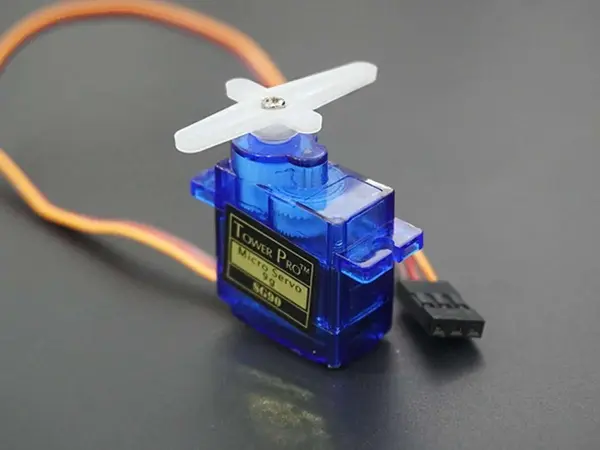
- SG90 micro servo motor
- AVR ATmega16 or ATmega32 microcontroller
- Potentiometer (for analog control)
- 8MHz crystal/internal clock (F_CPU 8000000UL)
- Power supply for MCU and servo
- Wiring/connectors (to connect servo, potentiometer, and MCU)
- Optional: breadboard or PCB for prototyping
Overview of Servo Motor
A servo motor is an electrically powered actuator that allows for precise control of angular rotation.
It provides controlled movement important for applications like robotic arms that require precision.
The rotation angle is dictated by a PWM (pulse-width modulation) signal sent to the motor.
Varying the width of the PWM pulses controls both angular position and direction of movement.
For the SG90 servo tested practically:
A duty cycle of ~0.52ms corresponded to -90° rotation
~1.4ms resulted in neutral/0° position
~2.4ms corresponded to full +90° rotation
Additional resources provided explain servo motor function and how to generate PWM signals on the ATmega MCU for rotational control.
Servo motors enable accurate angular positioning through closed-loop feedback using simple PWM control signals.
Generate PWM using AVR ATmega16
The duty cycle must vary from ~0.5ms to ~2.4ms, corresponding to the rotational range.
We can use Timer1 in fast PWM mode to generate the PWM waveform.
Timer1 will output PWM on PD5/OC1A pin.
Configure Timer1 for mode 14: TOP set by ICR1, overflow flag on match.
Use the 8MHz internal clock, prescaled by 64 for a 125KHz Timer1 clock frequency.
PWM frequency formula is PWM FREQ = Timer1 Clock / (TOP+1).
For a 50Hz PWM, set TOP = 125KHz / 50Hz – 1 = 2499
Then vary OCR1A from 0.5ms to 2.4ms to sweep duty cycle and control servo position from -90° to +90°.
By generating the appropriate PWM signal on Timer1, we can precisely control the angular position of the servo motor.
FPWM = FOSC / ( N * ( 1 + TOP ) )
Where N is pre-scaler divider i.e. 1, 8, 64, 256, or 1024.
- Hence to get 50Hz PWM frequency we need to load TOP value as 2499 so we get PWM frequency as,
FPWM = 8000000 / ( 64 * ( 1 + 2499 ) )
Timer1 is already configured to run at 125KHz by prescaling the 8MHz clock by 64.
We calculated the TOP value as 2499 to generate a 50Hz PWM signal.
ICR1 has been loaded with 2499.
To create a 1ms duty cycle pulse:
Each timer tick occurs at 1/125KHz = 8us
For a 1ms pulse we need 1ms/8us = 125 timer ticks
We set the OCR1A match value to indicate when to toggle the output
For a 125 timer tick pulse width, load OCR1A with 125
Loading OCR1A with 125 will generate a PWM signal with a 1ms high pulse width, achieving the desired 50% duty cycle.
Varying the OCR1A value allows adjusting the pulse width to control servo motor position.
By configuring ICR1 and OCR1A, Timer1 generates the correct PWM waveform to drive the servo at the specified position.
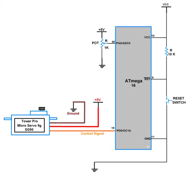
Connection Diagram of Micro Servo Motor SG90 with ATmega16/32
Now let’s program AVR ATmega16 to generate 50Hz PWM to control Servo Motor in an angle between -90° to +90° rotation.
- For SG90 Micro servo motor, here we get practically -90° at 0.52ms duty cycle Period of 50Hz PWM, so we are going to load OCR1A = 65.
- After 0° at 1.4ms duty cycle Period of 50Hz PWM, so we are going to load OCR1A = 175.
- And +90° at 2.4ms duty cycle Period of 50Hz PWM, so we are going to load OCR1A = 300.
Servo Motor SG90 Code for Atmega16/32
/*
* ATmega16_Servo_Motor
* http://www.electronicwings.com
*/
#define F_CPU 8000000UL /* Define CPU Frequency e.g. here its 8MHz */
#include <avr/io.h> /* Include AVR std. library file */
#include /* Include std. library file */
#include <util/delay.h> /* Include Delay header file */
int main(void)
{
DDRD |= (1<<PD5); /* Make OC1A pin as output */
TCNT1 = 0; /* Set timer1 count zero */
ICR1 = 2499; /* Set TOP count for timer1 in ICR1 register */
/* Set Fast PWM, TOP in ICR1, Clear OC1A on compare match, clk/64 */
TCCR1A = (1<<WGM11)|(1<<COM1A1);
TCCR1B = (1<<WGM12)|(1<<WGM13)|(1<<CS10)|(1<<CS11);
while(1)
{
OCR1A = 65; /* Set servo shaft at -90° position */
_delay_ms(1500);
OCR1A = 175; /* Set servo shaft at 0° position */
_delay_ms(1500);
OCR1A = 300; /* Set servo at +90° position */
_delay_ms(1500);
}
}
Control the Servo Motor by using Potentiometer With ATmega16/32
Configure Timer1 for 50Hz fast PWM output on PD5/OC1A as described previously.
Configure ADC channel 0 to read an external potentiometer input.
Continuously sample the ADC channel in a loop:
Read the 10-bit ADC value
Map it to a duty cycle range of 65-300 based on potentiometer position
Update the OCR1A register based on the mapped duty cycle value.
65 corresponds to a PWM pulse width of ~0.5ms (-90° position)
300 corresponds to a pulse width of ~2.4ms (+90° position)
Varying the potentiometer will change the ADC reading and update OCR1A
Sweeping the duty cycle to control the servo position between -90° to +90°
By sampling the potentiometer and updating OCR1A, the microcontroller generates a PWM linked to user input to precisely position the servo motor.
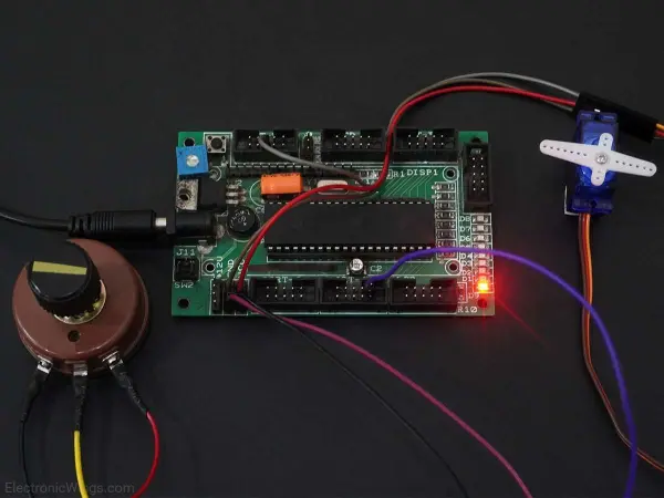
Connection Diagram of Servo Motor SG90 and Potentiometer with ATmega16/32
Potentiometer Controlled Servo Motor Code for ATmega16/32
/*
* ATmega16_Servo_Motor.c
* http://www.electronicwings.com
*/
#define F_CPU 8000000UL /* Define CPU Frequency e.g. here its 8MHz */
#include <avr/io.h> /* Include AVR std. library file */
#include /* Include std. library file */
#include <util/delay.h> /* Include Delay header file */
void ADC_Init() /* ADC Initialization function */
{
DDRA=0x00; /* Make ADC port as input */
ADCSRA = 0x87; /* Enable ADC, with freq/128 */
ADMUX = 0x40; /* Vref: Avcc, ADC channel: 0 */
}
int ADC_Read(char channel) /* ADC Read function */
{
ADMUX = 0x40 | (channel & 0x07); /* set input channel to read */
ADCSRA |= (1<<ADSC); /* Start ADC conversion */
/* Wait until end of conversion by polling ADC interrupt flag */
while (!(ADCSRA & (1<<ADIF)));
ADCSRA |= (1<<ADIF); /* Clear interrupt flag */
_delay_ms(1); /* Wait a little bit */
return ADCW; /* Return ADC word */
}
int main(void)
{
ADC_Init(); /* Initialize ADC */
DDRD |= (1<<PD5); /* Make OC1A pin as output */
TCNT1 = 0; /* Set timer1 count zero */
ICR1 = 2499; /* Set TOP count for timer1 in ICR1 register */
/* Set Fast PWM, TOP in ICR1, Clear OC1A on compare match, clk/64 */
TCCR1A = (1<<WGM11)|(1<<COM1A1);
TCCR1B = (1<<WGM12)|(1<<WGM13)|(1<<CS10)|(1<<CS11);
while(1)
{
OCR1A = 65 + (ADC_Read(0)/4.35);
/* Read ADC channel 0 and make count in between 65-300 i.e. 0.5-2.4 mSec duty cycle variation */
}
}
Video of Control Servo Motor SG90 using Potentiometer with Atmega16/32
- What pulse widths correspond to -90°, 0°, and +90° for the SG90 servo?
-90° ≈ 0.52ms, 0° ≈ 1.4ms, +90° ≈ 2.4ms. - How do you generate a 50Hz PWM using Timer1 on ATmega16?
Use Fast PWM mode with TOP in ICR1 set to 2499 and prescaler 64 so Timer1 clock is 125kHz giving 50Hz PWM. - Which pin outputs the PWM from Timer1 for servo control?
PWM is output on PD5 which is the OC1A pin. - What OCR1A values map to -90°, 0°, and +90° in the example?
Use OCR1A = 65 for -90°, OCR1A = 175 for 0°, and OCR1A = 300 for +90°. - How is a 1ms pulse width achieved with the configured Timer1?
With 8us timer ticks (125kHz), 1ms equals 125 ticks, so load OCR1A with 125 for a 1ms pulse. - How can a potentiometer control the servo position?
Read ADC channel 0, map the 10-bit ADC value to OCR1A range 65–300, and update OCR1A to vary pulse width and servo angle. - What ADC to OCR1A mapping formula is used in the example?
The code uses OCR1A = 65 + (ADC_Read(0)/4.35) to map ADC readings into the 65–300 range. - What prescaler and clock frequency are used for Timer1?
The ATmega uses the 8MHz clock with a prescaler of 64, producing a 125kHz Timer1 clock.