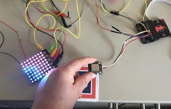
So in this project we are going to combine the MU vision sensor with a Kitronik Zip Tile. We will use the MU vision sensor to recognise colours and get the Zip Tile to show it to us.
We are going to use some of the techniques that we have used before. Mainly how to program a zip tile and how to serial connect the MU vision sensor to a micro:bit. You can find my instructables to that by folowing these links:
https://www.instructables.com/id/Microbit-Zip-Tile…
https://www.instructables.com/id/MU-Vision-Sensor-…
Supplies:
1 x Micro:bit
1 x Micro:bit breakout board – You can’t use elecfreaks motorbit, since its protection makes it impossible to power it directly from the zip tile.
4 x Jumper wires (Female-Female) to connect the MU vision sensor
3 x Jumper wires (Alligator-Female) to connect the Zip tile. Instead of an Alligator to female you can also use a normal alligator cable, a female-male or instead of a female-male you can use a female-female and male-male.
3 x 3M Screws Lenght is not that importent. You will get 5 of these screws with your zip tile.
3.5 – 5.3 V powersource. I am just using a 3 x AA batery holder with an on/off button
Step 1: Combining Cables(Skip If You Have Alligator-female Jumper Wire)
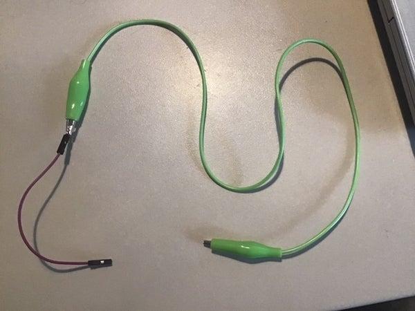
The first picture shows how to make an alligator-female jumper wire, by combining an alligator-alligator and male-female jumper wire.
The second picture shows how to make an alligator-female jumper wire, by combining an alligator-alligator, male-male and female-female jumper wire.
Step 2: Setting Up the MU Vision Sensor
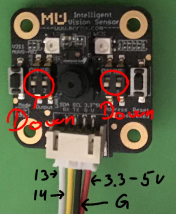
Before we start connecting anything we want to setup the sensor properly.
The Mu Vision sensor have 4 switches. The two on the left decides its output mode and the two one the right decides its address.
Since we want the address to be 00, both switches on the right should be turned off.
The different output modes are:
00 UART
01 I2C
10 Wifi data tansmission
11 Wifi picture transmission
We want to have a serial connection so we are going to work in the UART mode. That means that the two switches on the left should be on 00, so both should be on off. We could also have worked in I2C mode, but then your breakout board needs to have access to pin 19&20.
Step 3: Connecting the MU Sensor to the Breakout Board
Wiring is pretty easy, just use four jumper wires to connect the Mu sensor with our breakout board. Look at the picture in Step 2 for help.
Mu sensor -> Breakout board
RX-> pin 13
TX -> pin 14
G -> Ground
V -> 3.3-5V
Step 4: Connecting the Zip Tile to the Micro:bit and Power
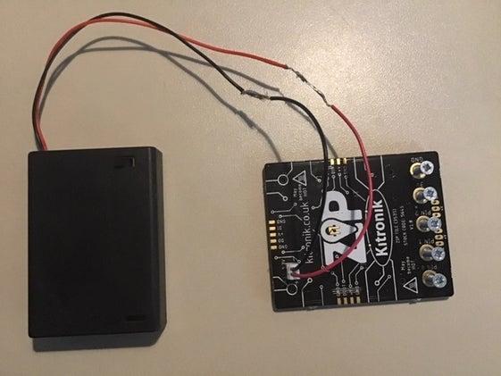
This project is going to draw its power through the zip tile, so we connect the battery pack to the zip tile and screw your M3 screws into the Pin 0, GND and Power.
I have put screws into all pin holes on the picture, but you only need Pin 0, GND and Power.-
Then you use your alligator-female jump wires to connect Pin 0, GND and Power to Pin 0, GND and Power on your breakout board. I have also marked Pin 1 and Pin 2 with alligator clips on the second picture, but you don’t need to do that nor do they need to be cnnected to the breakout board.
Wiring is pretty easy, just use four jumper wires to connect the Mu sensor with our breakout board. Look at the picture in Step 1 for help.
Zip tile -> Breakout board
Pin 0 -> Pin 0
GND -> GND
Power -> 3.3 V
Connect the power to the zip and not the micro:bit. The zip needs a lot more power than the micro:bit can provide, but it can power the micro:bit fairly easy. Build in safety measures prevents the zip from being power from the micro:bit.
If you power the micro:bit and zip from two different sources, then these safety meassures will sometimes engage and the zip will stop working. Don’t worry. Just remove all power and wait. After a few minuts it should be working again. This most often happens when you connect the micro:bit to your computer, without removing the power to the zip.
Step 5: Getting the Extensions
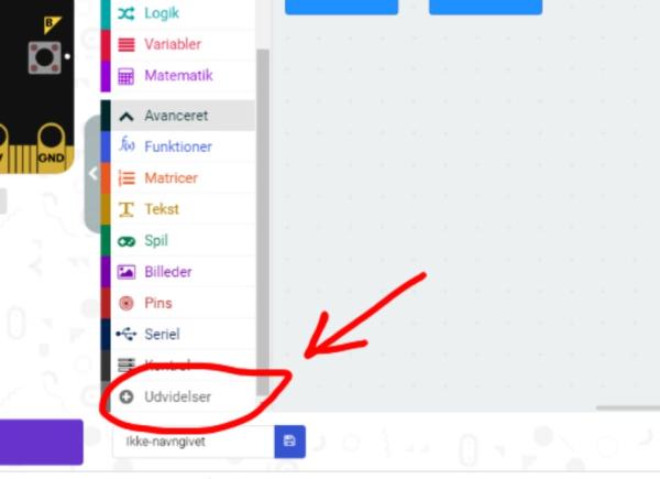
First you go to the Makecode editor and start a new project. You then go to “Advanced” and select “Extensions”. Be aware that since I am danish, these buttons have slightly different names in the pictures. In extensions you search for “zip tile” and select the only result you get.
You then go back into extensions and search for “Muvision” and select the only result you get.
Step 6: The Coordinate System Explained
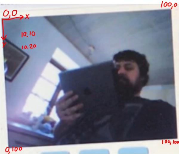
When we start programing, we are going to use the MU vision sensor coordinate system. Here the X value is the horizontal value. It goes from 0 to 100, with 0 being the left most point the sensor can see and 100 being the right most point.
The Y value is the vertical value. It goes from 0 to 100, with 0 being the top most point the sensor can see and 100 being the bottom most point.
Source: Micro:bit MU Vision Sensor and Zip Tile Combined