Summary of Microcontroller Based Smart Battery Charger
This article details a DIY smart battery charger using an ATMEGA8A microcontroller, designed specifically for 11.1V Li-ion batteries with auto-cutoff capabilities. The project features real-time monitoring via an LCD, audible alerts upon completion, and implements Constant Current/Constant Voltage charging protocols to ensure safety. The author built this to overcome limitations of commercial chargers and previous LM317-based designs, offering customizable firmware for different battery types.
Parts used in the Microcontroller Based Smart Battery Charger:
- ATMEGA8A microcontroller
- ACS714 5A current sensor (Pololu)
- IRF9540 MOSFETs (x2)
- 7805 voltage regulators (x2)
- 2N3904 transistors (x3)
- 1N5820 Schottky diodes (x2)
- 16x2 LCD display
- 330uH/2A power inductor
- 10uH inductor
- Various resistors (150R, 680R, 1k, 2k2, 10k, 22k, 5k pots)
- Capacitors (100uF, 470uF, 1000uF, 100n, 22p)
- PCB mount momentary push switches (x2)
- 20v Buzzer
- 2 pin Terminal block connectors (x2)
- Cabinet enclosure
- 19v laptop power supply
- Medium sized heat sink
- Banana connectors
The circuit what you are about to see is a smart battery charger based on ATMEGA8A with auto cut off.Different parameters are shown via a LCD during different charge states.Also the circuit will make sound via a buzzer upon charge completion.
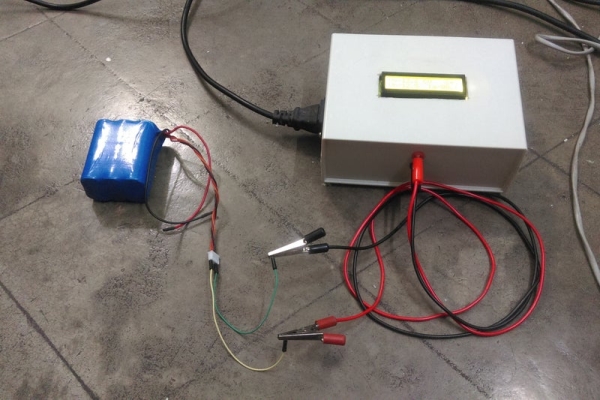
I built the charger basically to charge my 11.1v/4400maH Li-ion battery.The firmware is basically written to charge this particular battery type.You can upload your own charge protocol to fulfill your needs to charge other battery types.
As u know,smart battery chargers are readily available in the markets.But being an electronic enthusiast,it is always preferable for me to build my own rather than buying one which will have static/unchangeable functions.In this module,i have plans to upgrade in future so i have left space regarding that.
When i first bought my previous 11.1v/2200mah Li-ion battery,i searched for DIY battery chargers with smart control on the internet.But i found very limited resources.So for then,i made a battery charger based on LM317 and it worked really well for me.But as my previous battery died over time(for no reason),i bought another Li-ion battery of 11.1v/4400mah.But this time,the previous setup was inadequate to charge my new battery.To meet my requirement,i did some studying on the net,and was able to design my own smart charger.
I am sharing this as i think that many hobbyist/enthusiasts are out there who are really passionate about working on power electronics & microcontroller and also in a need to build a smart charger of their own.
Let’s take a quick look at how to charge a Li-ion battery.
Step 1: Charge Protocol for a Li-ion Battery
To charge Li-ion battery,certain conditions must be fulfilled.If we don’t maintain the conditions,either the battery will be undercharged or they will be set on fire(if overcharged) or will be permanently damaged.
There is a very good website to know everything necessary about different type of batteries and of course you know the name of the website if you are familiar with working on batteries…Yes,i am talking about batteryuniversity.com.
Here is the link to know the necessary details to charge a Li-ion battery.
If you are lazy enough to read all those theories,then the gist is as follows.
1.Full charge of a 3.7v Li-ion battery is 4.2v.In our case,11.1v Li-ion battery means 3 x 3.7v battery.For full charge,the battery must reach at 12.6v but for safety reason,we will charge it upto 12.5v.
2.When the battery is about to reach it’s full charge,then the current drawn by the battery from the charger drops to as low as 3% of the rated battery capacity.For ex,the battery capacity of my cell-pack is 4400mah.So when the battery will be fully charged,the current drawn by the battery will be reached as nearly 3%-5% of 4400ma i.e between 132 to 220ma.To safely stop the charge,charging will be stopped when the drawn current will go below 190ma(nearly 4% of rated capacity).
3.The total charge process is divided into two main parts 1-Constant current(CC mode), 2-Constant voltage(CV mode).(Also there is topping charge mode,but we will not implement that in our charger as the charger will notify the user upon full charge by alarming,then the battery must be disconnected from the charger)
CC mode –
In CC mode,the charger charges the battery with 0.5c or 1c charge rate.Now what the hell is 0.5c/1c????To be simple,if your battery capacity is for say 4400mah,then in CC mode,0.5c will be 2200ma and 1c will be 4400ma charge current.’c’ stands for charge/discharge rate.Some batteries also support 2c i.e in CC mode,you can set the charge current upto 2xbattery capacity but that is insane!!!!!
But to be safe,i will choose charge current of 1000ma for 4400mah battery i.e 0.22c.In this mode,the charger will monitor the current drawn by the battery independent of the charging voltage.i.e The charger will maintain 1A of charge current by increasing/decreasing the output voltage until the battery charge reaches to 12.4v.
CV mode –
Now as the battery voltage reaches to 12.4v,the charger will maintain 12.6 volt(independent of the current drawn by the battery) at it’s output.Now the charger will stop the charge cycle depending on two things.If the battery voltages crosses 12.5v and also if the charge current drops below 190ma(4% of rated battery capacity as previously explained),then the charge cycle will be stopped and a buzzer will be sounded.
Step 2: Schematic and Explanation
Now lets take a look at the circuit’s working.The schematic is attached in pdf format in the BIN.pdf file.
The input voltage of the circuit can be 19/20v.I have used a old laptop charger to get 19v.
J1 is a terminal connector to connect the circuit to input voltage source.Q1,D2,L1,C9 is forming a buck converter.Now what the hell is that???This is basically a DC to DC step down converter.In this type of converter,u can achieve the desired output voltage by varying the duty cycle.If you want to know more about buck converters,then visit this page.but to be frank,they are totally different from theory.To evaluate proper values of L1 & C9 for my requirements,it took 3 days of trial & error.If you are going to charge different batteries,then it can be possible that these values are going to change.
Q2 is the driver transistor for power mosfet Q1.R1 is a biasing resistor for Q1.We will feed the pwm signal in Q2’s base to control the output voltage.C13 is a decoupling cap.
Now the output is then fed to Q3.A question can be asked that “What is the use of Q3 here??”.The answer is pretty simple,It is acting like a simple switch.Whenever we will measure the voltage of the battery,we will shut off Q3 to disconnect the Charging voltage output from the buck converter.Q4 is the driver for Q3 with a biasing resistor R3.
Note that there is a diode D1 in the path.What the diode is doing here in the path??This answer is also very simple.Whenever the circuit will be disconnected from input power while battery attached at the output,the current from battery will flow in the reverse path via the body diodes of the MOSFET Q3 & Q1 and thus the U1 and U2 will get the battery voltage at their inputs and will power up the circuit from the battery voltage.To avoid this,D1 is used.
The output of the D1 is then fed to the current sensor input(IP+).This is a hall effect base current sensor i.e the current sensing part and the output part are isolated.The current sensor output(IP-) is then fed to the battery.Here R5,RV1,R6 are forming a voltage divider circuit to measure the battery voltage/output voltage.
The atmega8’s ADC is used here to measure the battery voltage and current.The ADC can measure max of 5v.But we will measure a max of 20v(with some headroom).In order to cut down the voltage to the ADC range,a 4:1 voltage divider is used.The pot(RV1) is used to fine tune/calibration.I will discuss it later.C6 is decoupling cap.
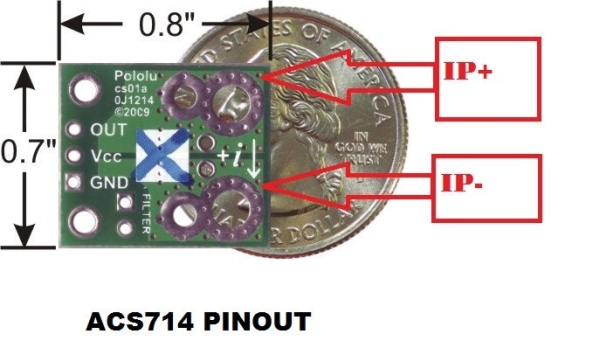
The output of the ACS714 current sensor is also fed to atmega8’s ADC0 pin.Via this ACS714 sensor,we will measure the current.I have a breakout board from pololu of 5A version and works really great.I will talk about in the next stage on how to measure the current.
The LCD is a normal 16×2 lcd.The lcd used here is configured in 4 bit mode as the pin count of atmega8 is limited.RV2 is the brightness adjustment pot for the LCD.
The atmega8 is clocked at 16mhz with a external crystal X1 with two decoupling caps C10/11.The ADC unit of the atmega8 is being powered via the Avcc pin through a 10uH inductor.C7,C8 are decoupling caps connected to Agnd.Place them as closely as possible to the Avcc and Aref correspondingly while making PCB.Notice that the Agnd pin is not shown in the circuit.The Agnd pin will be connected to ground.
I have configured the ADC of the atmega8 to use external Vref i.e we will supply the reference voltage via the Aref pin.The main reason behind this to achieve max possible reading accuracy.The internal 2.56v reference voltage is not so much great in avrs.That’s why i configured it externally.Now here is a thing to notice.The 7805(U2) is supplying only the ACS714 sensor and the Aref pin of atmega8.This is to maintain optimum accuracy.The ACS714 gives a stable 2.5v output voltage when there is no current flow through it.But for say,if the supply voltage of the ACS714 will be lowered(say 4.7v) then the no current output voltage(2.5v) will also gets lowered and it will create inappropriate/erroneous current reading.Also as we are measuring the voltage with respect to Vref,then the reference voltage on Aref must be error free and stable.That’s why we need a stable 5v.
If we would power the ACS714 & Aref from the U1 which is supplying the atmega8 and the lcd,then there would be substanial voltage drop at U1’s output and the ampere and voltage reading would be erroneous.That’s why U2 is used here to eliminate the error by supplying a stable 5v to Aref and ACS714 only.
S1 is pressed to calibrate the voltage reading.S2 is reserved for future use.You can either add/not add this button according to your choice.
Step 3: Functioning…..
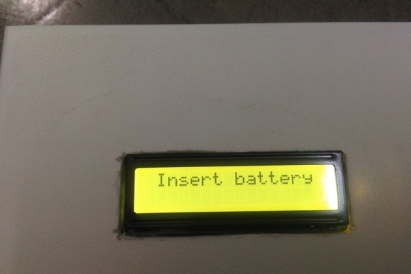
At being powered up,the atmega8 will turn on the buck converter by giving 25% pwm output at the Q2’s base.In turn,Q2 will then drive Q1 and buck converter will be started.Q3 will be driven off to disconnect the buck converter’s output and the battery.The atmega8 then reads the battery voltage via the the resistor divider.If no battery is connected,then the atmega8 shows a message “Insert battery” via 16×2 lcd and waits for the battery.If a battery is then attached,the atmega8 will check the voltage.If the voltage is lower than 9v,then the atmega8 will show “Faulty battery” on the 16×2 lcd.
If a battery with more than 9v found,then the charger will first enter into CC mode and turn on the output mosfet Q3.Charger mode (CC) will be updated to display immediately.If the battery voltage is found more than 12.4v,then the mega8 will immediately leave the CC mode and will enter into CV mode.If the battery voltage is less than 12.4v,then the mega8 will mantain 1A charge current by increasing/decreasing output voltage of the buck converter by varying duty cycle of the pwm.The charge current will be read by the ACS714 current sensor.The buck output voltage,charge current,PWM duty cycle will be periodically updated in the lcd.
.The battery voltage will be checked by turning off Q3 after every 500ms interval.The battery voltage will be immediately updated to the lcd.
If the battery voltage gets more than 12.4 volt during charging,then the mega8 will leave the CC mode and will enter into CV mode.Mode status will be immediately updated to the lcd.
Then the mega8 will maintain the output voltage of 12.6 volt by varying the duty cycle of the buck.Here the battery voltage will be checked after every 1s interval.As soon as the battery voltage will be greater than 12.5v,then it will be checked if the drawn current is below 190ma.If both the conditions are met,then the charge cycle will be stopped by permanently turning off Q3 and a buzzer will be sounded by turning on Q5.Also mega8 will show “Charge complete”via the lcd.
Step 4: Parts Required
Listed below are the required parts to complete the project.Please refer to datasheets for pinout.Only crucial parts datasheet link provided
1) ATMEGA8A x 1.(datasheet)
2) ACS714 5A current sensor from Pololu x 1 (I strongly recommend to use the sensor from Pololu as they are the best accurate among all other sensors i’ve used.You can find it here).Pinout is described in the image.
3) IRF9540 x 2.(datasheet)
4) 7805 x 2(recommended from Toshiba genuinespare as they give the most stable 5v output).(datasheet)
5) 2n3904 x 3.(datasheet)
6) 1n5820 schottky x 2.(datasheet)
7) 16×2 LCD x 1.(datasheet)
8) 330uH/2A power inductor x 1 (recommended from coilmaster)
9) 10uH inductor x 1(small)
10) Resistors -(All resistors are 1% MFR type)
150R x 3
680R x 2
1k x 1
2k2 x 1
10k x 2
22k x 1
5k pot x 2(pcb mount type)
11) Capacitors
Note: I didn’t use C4.There is no need to use it if you are using Laptop power supply/Regulated power supply as 19v power source
100uF/25v x 3
470uF/25v x 1
1000uF/25v x 1
100n x 8
22p x 2
12) PCB mount momentary push switch x 2
13) 20v Buzzer x 1
14) 2 pin Terminal block connector x 2
15) Cabinet(I used a cabinet like this.).You can use whatever you like.
16) 19v laptop power supply(I modified a hp laptop power supply,You can use any type power supply as you want.If you want to build one,then visit my this instructables.)
17)Medium sized heat sink for U1 & Q1.You can use this type.Or you can refer to my circuit pictures.But be sure to use heat sink for both of them.
18) Banana connector – Female(Black & Red) x 1 + Male(Black & Red)(depending on your need of connectors)
Step 5: Time to Calculate……
Voltage measurement calculation :
The max voltage,we will measure using the atmega8 adc is 20v.But atmega8’s adc can measure max of 5v.So in order to make20v within 5v range,a 4:1 voltage divider is used here(as 20v/4=5v).So we could implement that by simply using two resistors,but in our case,i’ve added a pot in between two fixed resistors so that we can manually adjust the accuracy by turning the pot.The resolution of the ADC is 10bit i.e the adc will represent the 0v to 5v as 0 to 1023 decimal numbers or 00h to 3FFh.(‘h’ stands for hex numbers).The reference is set to 5v externally via the Aref pin.
So the measured voltage = (adc reading) x (Vref=5v) x (resistor divider factor i.e 4 in this case) / (max adc reading i.e 1023 for 10bit adc).
Suppose we get a adc reading of 512.Then the measured voltage will be –
(512 x 5 x 4) / 1023 = 10v
Current measurement calculation :
The ACS714 will give 2.5v stable output at the out pin when no current will flow from IP+ towards IP-.It will give 185mv/A over the 2.5v i.e for say,if 3A current is flowing through the circuit,the acs714 will give 2.5v+(0.185 x 3)v = 3.055v at it’s out pin.
So the current measurement formula is as follows –
Measured current=(((adc reading)*(Vref=5v)/1023)-2.5)/0.185.
for say,the adc reading is 700,then the measured current will be – (((700 x 5)/1023) – 2.5)/0.185 = 4.98A.
Step 6: The Software
The software is coded in Winavr using GCC.I have modularized the code i.e i’ve created different libraries like adc library,lcd library etc.The adc library contains the necessary commands to setup & interaction with the adc.The lcd library contains all the functions to drive the 16×2 lcd.You can also use the lcd_updated _library.c as the start up sequence of the lcd is modified in this library.If you want to use the updated library,then rename it with lcd.c
The main.c file contains the main functions.The charging protocol for li-ion is written here.Please define the ref_volt in the main.c by measuring the output of U2(7805) with a precise multimeter to get accurate readings as the calculations are based on it.
You can simply burn the .hex file directly in your mega8 to bypass the headche.
For those,who want to write another charge protocol,i have put enough comments by which even a child can understand whats going on for each line execution.Just you have to write your own protocol for different battery type.If you are using Li-ion of different voltage,you have to only change the parameters.(Though this is not tested for other li-ion/other battery type.You have to work it out by yourself).
I strongly recommend not to build this circuit,if this is your first project or you are new to microcontroller/power electronics.
I have uploaded each and every file as it’s original format except the
Makefile as it is creating problem to open.I have uploaded it in .txt format.Just copy the content and paste it into a new Makefile and build the whole project.Voila….you are ready to burn the hex file.
Source: Microcontroller Based Smart Battery Charger
- How is the input voltage provided to the circuit?
The input voltage can be 19v or 20v, typically sourced from a modified laptop charger connected via terminal connector J1. - What is the purpose of diode D1 in the circuit?
D1 prevents current from flowing in reverse from the battery through the MOSFET body diodes to power the microcontroller when disconnected from the main input. - Why are two separate 7805 regulators used instead of one?
One regulator powers the microcontroller and LCD, while the second provides a stable 5v specifically for the ACS714 sensor and Aref pin to ensure measurement accuracy. - How does the charger determine when to stop charging?
The charge cycle stops when the battery voltage exceeds 12.5v and the drawn current drops below 190ma, triggering a buzzer and LCD message. - What happens if a battery voltage lower than 9v is detected?
If the battery voltage is lower than 9v, the microcontroller displays "Faulty battery" on the LCD and does not proceed with charging. - How is the battery voltage measured accurately by the ADC?
A 4:1 voltage divider is used to scale the maximum 20v battery voltage down to the 5v range readable by the ATMEGA8's ADC. - Can this charger be used for battery types other than 11.1V Li-ion?
Yes, users can upload their own charge protocol by modifying the parameters in the firmware to suit different battery voltages and types. - What is the recommended charge current for the 4400mah battery described?
The author chose a safe charge current of 1000ma (0.22c) for the 4400mah battery during the Constant Current mode. - How is the brightness of the LCD adjusted?
The brightness is adjusted using pot RV2, which is part of the LCD configuration circuit. - What software environment was used to write the firmware?
The software was coded in Winavr using GCC, with modular libraries created for the ADC and LCD interactions.