Now quite a popular topic with Cell Phone Control with Microchip pic series for those who want to do these types of projects that could give clues will limp a few projects, including projects… Electronics Projects,Microcontroller GSM Alarm and Control Circuits “avr project, microcontroller projects, “
Now quite a popular topic with Cell Phone Control with Microchip pic series for those who want to do these types of projects that could give clues will limp a few projects, including projects located in Atmella in 1
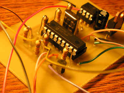
Pcb circuit connected pc with AT90S2313 asm hex file and available software
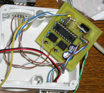
Emergency equipment is often equipped are various signs of tampering. The easiest is to run the audible signal or optical, the more advanced can given its status over the Internet or telephone. Presented in this article to your amateur alarm, which can send information on the attached by short text messages, so-called SMS. For model needs the company I used GSM modem Wavecom, but you can use any phone phone. Perhaps its use will require a solution to the problem of power and how encoding text messages, but it is possible and feasible in terms of electronics workshop – amateur.
The whole program has been constructed and compiled by AVR STUDIO 4. This is a complete environment for writing and applications for the AVR microcontrollers. The line RESET, MISO, MOSI and SCK przylutowałem microcontroller interface and programmer using ISP program and tested layout. This is a very comfortable not only for the amateur electronics, method. Allows you to run applications in real – its operating environment. The program occupies 128 bytes of EEPROM memory in the variables defined by the user. Their list can be found in Table takes 1,019 words double-byte, 2038 is 2048 bytes of program memory AT90S2313. Unfortunately, there is already too much space to implement the new functions or more messages. You can only be done
cost of removing or optimizing existing ones.
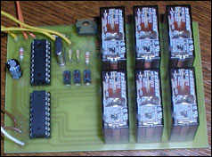
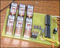
It is a device that will include / exclude consumers when he sent the SMS. I did. The device consists of a PIC microcontroller, one ULN2803A (order transistor) power relays, and 6 relays. Of course, a few resistors and capacitors, three prekidačića, crystal and two LE diodice. The device was tested on Siemens phones, S25 and C35i. You should work with the other, and with all other GSM device which can be attached to the serial communication. Such devices are, for example.: All-Ericsson, and only with them I have not yet tested.
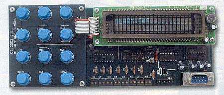
GSM Call Alarm is a device that uses a number of target position Siemens or Ericsson Mobile Phone (19200 bauds RS232) and sensory input is 1 and one entry – the state. If state = 0V then the device is “active” and follow the state senzorskog inputs. The device is “disabled” otpajanjem on / off (the state) with the mass of inputs (0V), or connect to the + half of power. Sensory input also respond to 0V.
SMS Alarm is a very simple device. To send a message uses a Siemens phone has 5 inputs – is sending 5 different messages. For each sensor uprogramiramo appropriate message you wish to receive the mobile when it is activated. Programming is done via the PC’s corresponding program which is attached in the archive.
Source:GSM ALARM AND CONTROL CIRCUITS Microcontroller GSM Alarm and Control Circuits: microcontroller-gsm-alarm-and-control-circuits.raralternative link3