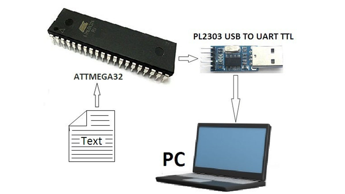
Summary of MICROCONTROLLER to PC Communication Via PL2303 (USB TO UART TTL) Converter
This article details interfacing an Atmega32 microcontroller with a PC using a PL2303 USB-to-UART converter, as modern PCs lack native serial ports. It explains the differences between parallel and serial communication, RS-232 standards, and voltage levels. The project involves connecting the PL2303 module to the MCU, configuring drivers, and writing C code in WinAvr/Cygwin to display "Hello World" on an LCD while transmitting data to a terminal like PuTTY at 9600 baud.
Parts used in the Microcontroller to PC Communication Project:
- Atmega32 Microcontroller
- PL2303 USB to UART TTL Converter Breakout Board
- RS232 Serial Interface
- LCD Display (HD44780 compatible)
- PC with DDR3 support
- WinAvr 2008 Development Environment
- Cygwin
- PuTTY Terminal Software
- PL2303 Prolific Driver
Device communication is done in two ways:
- parallel and
- serial.
In the parallel mode, data transfer is fast and uses more number of lines. This mode is good for short range data transfer.
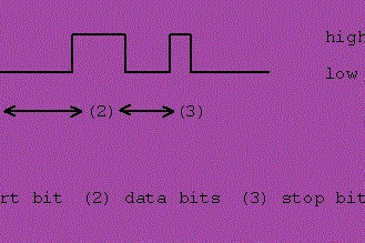
But, Serial communication uses only one or two data lines to transfer data and is generally used for long distance communication. In serial communication the data is sent as one bit at a time.
My motto is to describes the interfacing of micro-controller (Atmega32) with a computer via serial port, RS232. But at present my computer system(DDR3 supported) does not have any serial port(DB9). So, I am trying to communicate MCU through a USB to UART Serial Converter breakout board. There are many USB to UART Serial Converters are available, such as: cp2102/4, pl2303, FT232RL, CH340G etc. I have chosen pL2303 bcz. of availability and cost.
Step 1: PL2303 (USB TO UART TTL CONVERTER) DETAILS
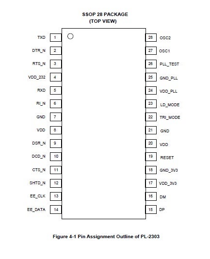
The PL-2303 operates as a bridge between one USB port and one standard RS232 Serial port. The two large on-chip buffers accommodate data flow from two different buses. The USB bulk-type data is adopted for maximum data transfer. Automatic handshake is supported at the Serial port. With these, a much higher baud rate can be achieved compared to the legacy UART controller.
This device is also compliant with USB power management and remote wakeup scheme. Only minimum power is consumed from the host during Suspend. By integrating all the function in a SSOP-28 package. This chip is suitable for cable embedding. Users just simply hook the cable into PC or hub’s USB port, and then they can connect to any RS-232 devices.
PL2303 – FATURES
Fully compliant with USB Specification v1.1 and USB CDC v1.1
? Supports RS232 Serial interface
? Supports automatic handshake mode
? Supports Remote wake-up and power management
? 256-bytes buffer each for upstream and downstream data flow
? Supports default ROM or external EEPROM for device configuration
? On-chip USB transceiver
? On-chip crystal oscillator running at 12MHz
? Supports Windows 98/SE, ME, 2000, XP, Windows CE3.0, CE .NET, Linux, and Mac OS
? Designed for Windows XP/2000 Certified Logo Drivers
? USB-IF Logo Compliant with TID 10240590
? 28-Pin SSOP package
Step 2: Serial Communication Using RS-232
Data Communication:
Communication between/among systems physically or remotely.
Types of Data Communication
- Point-to-point Communication (RS-232)
- Bus-based Communication (I^2C,SPI,PCI,PCI-EXPRESS, USB, SATA)
Speed Rates
RS-232 < I^2C < SPI < PCI < PCI-EXPRESS < USB < SATA
PC serial port:
Serial communication means transferring a single bit at a time. We can connect a mouse, a modem, a printer, a plotter, another PC, dongles, etc. But its usage (both software and hardware) is a secret to users. But it is not difficult to understand how to connect devices to it and how to program it.
RS-232 is a standard communication protocol for linking computer and its peripheral devices to allow serial data exchange. In simple terms RS232 defines the voltage for the path used for data exchange between the devices. It specifies common voltage and signal level, common pin wire configuration and minimum, amount of control signals. As mentioned above this standard was designed with specification for electromagnetically teletypewriter and modem system.
Serial Data Transmission Types:
- Simplex mode: Sender——————–>Receiver(T) one-way (as, sensor data)
- Half Duplex mode: Sender<========>Receiver(T/R), once at a time (as, radio-system)
- Full Duplex mode: Sender<========>Receiver (T&R), two way simultaneously (as, telephone)
Problem:
IT didn’t define elements such as—
>>character encoding,
>>framing of characters,
>>error detection protocols etc
that are essential features when data transfer takes place between a computer and a printer. Without which it could not be adopted to transfer data between a computer and a printer.
Solution:
A single integrated circuit called as UART known as universal asynchronous receiver/transmitter is used in conjunction with RS232.
PC is capable of serial transmission at up to 115,200 bps (step size of 8.68 microseconds!). Typical rates are 300 bps, 1200 bps, 2400 bps and 9600 bps, up to 115,200 bps
The Physical Transmission:
The RS232C port of PC uses voltages:
>>MARK/LOW is signaled by -3 V to -5 V and represents a logical one(1).
>>SPACE/HIGH is signaled by +3 V to +5V and represents a logical zero(0).
>>Three lines (RX, TX & GND) are at least needed..
RxD (Received data):
The RxD pin is the Data Receive pin. This is the pin where the receiver receives data.
TxD (Transmitted data):
The TxD pin is the Data Transmit pin. This is the pin through which data is transmitted to the receiver.
Handshaking
- Automated process of setting communication parameters
- Parameters are:-
- transfer rate
- parity
- even
- odd
- interrupts
- Ex- Modem, Printers
- Helps connect heterogeneous systems over a communication channel.
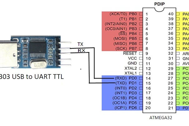
Step 3: Connection and Coding
PROGRAMS:
Just connect according to the diagram.
Tools required:
- WinAvr 2008
- Cygwin
——————————————–
Same code can run on avrstudio also.
Codes are given as below:-
lcd_io.h
#ifndef LCD_IO_H<br>#define LCD_IO_H</p><p>#include
#include </p><p>/*##############################*/
/* CONFIGURATION BLOCK STARTS HERE. Change these definitions to adapt setting */
/*#################################*</p><p>********/
/* GLOBAL SETTINGS (settings described here are applyied everywhere)*/
/*******************************/
/*  */#ifndef F_CPU
#define F_CPU                     8000000   /* CPU CLOCK FREQUENCY         */
#endif</p><p>/* 6=6 PIN I/O, 2=2 PIN I/O, 3=I2C, 7=multi lcd */
#define LCD_IO_MODE               6</p><p>/* 1 = Auto line feed, 0 = no Auto line feed */
#define LCD_AUTO_LINE_FEED        0</p><p>/* THE TYPICAL TIME THE LCD NEEDS TO COMPLETE A COMMAND  */
#define LCD_DELAY_TIME_US         100</p><p>/* THE E PULSE WIDTH IN MICROSECONDS (Timing is accurate)*/
#define LCD_E_PULSE_WIDTH_US      1</p><p>/* The decimal point punctuation mark char */
#define LCD_DECIMAL_POINT         '.'</p><p>/* WAYS TO REDUCE CODE SIZE BY NOT COMPILING UNWANTED FUNCTIONS OR CODE
 * PORTIONS */
/* 1=function available, 0=not available. */
#define LCD_PUT_I_NEEDED          1
#define LCD_PUT*/
/*     START OF SELECTED MODE CONFIGURATION BLOCK      */
/********************************************************/
/*    START OF MODE 6 CONFIGURATION BLOCK              */
#if LCD_IO_MODE == 6
/**********************************************/

/* MODE 6 IN GLOBAL
  SETTINGS  If you plan to use just one port for all pins then just edit
  "LCD_PORT" otherwise you must specify the port of each lcd signal. the
  port(s) must be able to function as output. It can be any combination!  PUT
  YOUR LCD PORT LETTER HERE USING CAPITAL LETTER (A,B,C,D...etc)
*/
#define LCD_CHARS_PER_LINE       16        /* visible chars per lcd line */
#define LCD_LINES                2         /* visible lines ** 1=the DDR's used are saved and restored */
#define LCD_MULTIPLEX_ENABLE     0
/* 0=use delay, 1=read busy flag & data (7 pins needed) */
#define LCD_READ_REQUIRED        0/*
   This enables the backup functions that backup and restore the lcd display.
   LCD_LINES X LCD_CHARS_PER_LINE bytes are needed (That means 80 bytes for a 4
   x 20 lcd display). 0=lcd screen backup location is eeprom, 1=lcd screen
   backup location is ram.
   If you need to backup less, use the lcd_getc function.  When using the
   lcd_getc() function the Address Counter (AC) is auto incremented or
   decremented according to the ENTRY MODE selected during initialization, just
   like the lcd_putc() function works, so when doing a sequential read, there
   is no need to reposition the cursor each time a read is performed.  The
   backup & restore settings are valid only if LCD_READ_REQUIRED == 1
*/
#define LCD_BACKUP_REQUIRED      0
#define LCD_BACKUP_LOCATION      0
#define LCD_PORT                 C
#define LCD_DATA4_PORT           D         /* port for data 0 pin  */
#define LCD_D4_PIN               7         /* AVR port pin number */

#define LCD_DATA5_PORT           D         /* port for data 1 pin  */
#define LCD_D5_PIN               6         /* AVR port pin number */

#define LCD_DATA6_PORT           D         /* port for data 2 pin  */
#define LCD_D6_PIN               5         /* AVR port pin number */
#define LCD_DATA7_PORT           B         /* port for data 3 pin  */
#define LCD_D7_PIN               3         /* AVR port pin number */
#define LCD_RS_SIGNAL_PORT       B         /* port for RS line */
#define LCD_RS_PIN               1         /* AVR port pin number */
#define LCD_E_SIGNAL_PORT        B         /* port for Enable line */
#define LCD_E_PIN                2         /* AVR port pin number */

/* YOU NEED TO EDIT  "LCD_RW_SIGNAL_PORT" AND "LCD_RW_PIN" ONLY IF * "LCD_READ_REQUIRED == 1" */
#if LCD_READ_REQUIRED == 0
#define LCD_RW_SIGNAL_PORT       LCD_PORT         /* port for R/W line */
#define LCD_RW_PIN               6                /* AVR port pin number */
#endif

#endif  /* #if LCD_IO_MODE == 6 */
/**************************************************************/
/*            END OF 6 PIN CONFIGURATION BLOCK               */
/**************************************************************/
/*              CONFIGURATION BLOCK ENDS HERE.               */
/*##################** you shouldn't need to change anything below this line ***********************/
/*                  HD44780 DDRAM PARAMETERS                              */
/********************************************/#define LCD_LINE_LENGTH          0x40     /* internal line length */
#define LCD_START_LINE1          0x00     /* DDRAM address of first char of
											 line 1 */
#define LCD_START_LINE2          0x40     /* DDRAM address of first char of
											 line 2 */
#define LCD_START_LINE3          0x14     /* DDRAM address of first char of
											 line 3 */
#define LCD_START_LINE4          0x54     /* DDRAM address of first char of
											 line 4 **************************************************************/
/*    INSTRUCTION REGISTER BIT POSITIONS AND COMBINATIONS    */
/*************************************************************/
#define LCD_CLR                  0      /* DB0: clear display */
#define LCD_HOME                 1      /* DB1: return to home position */
#define LCD_ENTRY_MODE           2      /* DB2: set entry mode */
#define LCD_ENTRY_INC            1      /*   DB1: 1=increment, 0=decrement  */
#define LCD_ENTRY_SHIFT          0      /*   DB2: 1=display shift on        */
#define LCD_ON                   3      /* DB3: turn lcd/cursor on */
#define LCD_ON_DISPLAY           2      /*   DB2: turn display on */
#define LCD_ON_CURSOR            1      /*   DB1: turn cursor on */
#define LCD_ON_BLINK             0      /*   DB0: blinking cursor ? */
#define LCD_MOVE                 4      /* DB4: move cursor/display */
#define LCD_MOVE_DISP            3      /*   DB3: move display (0-> cursor) ? */
#define LCD_MOVE_RIGHT           2      /*   DB2: move right (0-> left) ? */
#define LCD_FUNCTION             5      /* DB5: function set */
#define LCD_FUNCTION_8BIT        4      /*   DB4: set 8BIT mode (0->4BIT mode)
										 */
#define LCD_FUNCTION_2LINES      3      /*   DB3: two lines (0->one line) */
#define LCD_FUNCTION_10DOTS      2      /*   DB2: 5x10 font (0->5x7 font) */#define LCD_CGRAM                6      /* DB6: set CG RAM address */

#define LCD_DDRAM                7      /* DB7: set DD RAM address */</p><p>#define LCD_BUSY                 7      /* DB7: LCD is busy ** function set: set interface data length and number of display lines */
#define LCD_FUNCTION_4BIT_1LINE  0x20   /* 4-bit interface, single line, 5x7
										   dots */
#define LCD_FUNCTION_4BIT_2LINES 0x28   /* 4-bit interface, dual line,   5x7
										   dots */
#define LCD_FUNCTION_8BIT_1LINE  0x30   /* 8-bit interface, single line, 5x7
										   dots */
#define LCD_FUNCTION_8BIT_2LINES 0x38   /* 8-bit interface, dual line,   5x7
										   dots *</p><p>* Lcd default mode used in this driver */
#define LCD_MODE_DEFAULT         ((1</******************************************/
/*                     LCD COMMANDS (CAN BE USED WITH "lcd_command(cmd);")      */
/******************************************/
/* set entry mode: display shift on/off, dec/inc cursor move direction */
#define LCD_ENTRY_DEC            0x04   /* display shift off, dec cursor move dir */
#define LCD_ENTRY_DEC_SHIFT      0x05   /* display shift on,  dec cursor move dir */
#define LCD_ENTRY_INC_           0x06   /* display shift off, inc cursor move dir */
#define LCD_ENTRY_INC_SHIFT      0x07   /* display shift on,  inc cursor move dir ** display on/off, cursor on/off, blinking char at cursor position */
#define LCD_DISP_OFF             0x08   /* display off                            */
#define LCD_DISP_ON              0x0C   /* display on, cursor off                 */
#define LCD_DISP_ON_BLINK        0x0D   /* display on, cursor off, blink char     */
#define LCD_DISP_ON_CURSOR       0x0E   /* display on, cursor on                  */
#define LCD_DISP_ON_CURSOR_BLINK 0x0F   /* display on, cursor on, blink char      */
#define LCD_CLEAR_SCREEN         (1<</* move cursor/shift display */
#define LCD_MOVE_CURSOR_LEFT     0x10   /* move cursor left  (decrement) */
#define LCD_MOVE_CURSOR_RIGHT    0x14   /* move cursor right (increment) */
#define LCD_MOVE_DISP_LEFT       0x18   /* shift display left            */
#define LCD_MOVE_DISP_RIGHT      0x1C   /* shift display right           *>*****************************************/
/*      LCD USEFULL DEFINITIONS             */
/*******************************************/
#ifndef LOCATION_IS_RAM
#define LOCATION_IS_RAM          1
#endif
#ifndef LOCATION_IS_EEPROM
#define LOCATION_IS_EEPROM       2
#endif
#ifndef LOCATION_IS_FLASH
#define LOCATION_IS_FLASH        3
#endif

#if LCD_IO_MODE == 7 || LCD_IO_MODE == 3
/* lcd_select() argument values */
#define ALL                      0
#define LCD_0                    0
#if NUMBER_OF_LCD_UNITS >= 2
#define LCD_1                    1
#endif
#if NUMBER_OF_LCD_UNITS >= 3
#define LCD_2                    2
#endif
#if NUMBER_OF_LCD_UNITS >= 4
#define LCD_3                    3
#endif
#if NUMBER_OF_LCD_UNITS >= 5
#define LCD_4                    4
#endif
#if NUMBER_OF_LCD_UNITS >= 6
#define LCD_5                    5
#endif
#if NUMBER_OF_LCD_UNITS >= 7
#define LCD_6                    6
#endif
#if NUMBER_OF_LCD_UNITS >= 8
#define LCD_7                    7
#endif</p><p>#endif /* #if LCD_IO_MODE == 7 ****/
/*             PUBLIC FUNCTION PROTOTYPES      */
/********************************************
  MANUAL LCD INITIALIZATION IS NOT NEEDED ANYMORE. IT IS DONE AUTOMATICALLY!
  An exception is when "LCD_SAVE_MORE_CODE_SPACE == 1". Then a call to
  "lcd_init()" is needed.
*/
/* HIGH level functions */
extern void          lcd_init(void);
#if NUMBER_OF_LCD_UNITS >= 2
extern void          select_lcd(unsigned char lcd_unit);
#endif
extern void          lcd_command(unsigned char cmd);
extern void          lcd_gotoxy(unsigned char lcd_x, unsigned char lcd_y);
extern void          lcd_putc(unsigned char c);
extern void          lcd_puts(const unsigned char *s);
#if LCD_PUT_I_NEEDED == 1
extern void          lcd_put_i(int value, unsigned char dot_position, unsigned char number_of_chars) ;
#endif
#if LCD_PUTS_P_NEEDED == 1
extern void          lcd_puts_p(const unsigned char *progmem_s);
#endif
#if LCD_PUTS_E_NEEDED == 1
extern void          lcd_puts_e(unsigned char *eeprom_s);
#endif
#if LCD_PUTC_CGRAM_NEEDED == 1
extern void          lcd_putc_cgram(const unsigned char *user_char, unsigned char char_position);
#endif
#if LCD_CLRLINE_NEEDED == 1
extern void          lcd_clrline(unsigned char line);
#endif
#if LCD_GETXY_NEEDED == 1
/*
    The return value of the "lcd_getxy()" function is an integer,
    with the high byte containing the current line number (y) and the low byte
    containing the char position in that line (x).
    If the lower byte has a value of 20 that means that you filled that line.
    This position result can only happen when no lcd reading is available.
    When lcd reading is available the maximum x == 19.
*/
extern unsigned int  lcd_getxy(void);
#endif
#if  LCD_READ_REQUIRED == 1
extern unsigned char lcd_getc(void);
#if LCD_BACKUP_REQUIRED == 1
extern void          lcd_backup_scr(void);
extern void          lcd_restore_scr(void);
#endif
#endif/*
   The lcd_puti is actually a macro of the lcd_put_i(x,y,z) function with z set
   to 0xFF. x= the signed 16 bit number, y= the decimal digits wanted and z
   the number of reserved lcd chars.  x must be between -32767 and +32767 and y
   from 0 to 5 max. z bigger than 8 is ignored and the number gets as many lcd
   chars as it needs (325 will get 3 lcd chars and -1 will get 2 lcd chars).
   Maximum char count case is lcd_put_i(-32767,5,8);. The display should show
   -0,32767 (8 chars) The chars are now left alligned so if you reserve lets
   say 5 digits for a 3 digit number like 325 then the display will show
   325+space+space (Of course you can't see the spaces).More examples:  a) We give the command lcd_puti(var_name,0); and var=325
      The display will show 325
   b) We give the command lcd_puti(var_name,2); and var=325
      The display will show 3,25
   c) We give the command lcd_put_i(var_name,3,5); and var=325
      The display will show 0,325
   d) We give the command lcd_put_i(var_name,4,4); and var=325
	  the whole number is 0,0325 but since you reserved only 4 digits the
	  display will show  0,03
   e) We give the command lcd_put_i(var_name,1,6); and var=(-325)
      The display will show -32,5+space
   f) We give the command lcd_put_i(var_name,1,3); and var=(-325)
	  the whole number is -32,5 but since you reserved only 3 digits the
	  display will show -32
 *</p><p>*******************************************/
/*           FUNCTION RESEMBLING MACROS            */
/***************************************************/
</p><p>#define lcd_clrscr()            lcd_command(LCD_CLEAR_SCREEN)
#define lcd_home()              lcd_command(LCD_RETURN_HOME)
#define lcd_puti(x,y)           lcd_put_i(x,y,0xFF)
#define lcd_fill_cgram(array)   lcd_putc_cgram((const unsigned char*)array, sizeof(array))</p><p>#if LCD_SAVE_MORE_CODE_SPACE == 1
#define lcd_goto_cgram(char)    lcd_command((1<</p><p>#endif //LCD_IO_H
/*########################################*/
/*                 T H E   E N D          */
/*######################################*/</p>
UART.h
<strong><u><br></u></strong><p>#include  <avr/pgmspace.h><br></p><p>#define UART_BAUD_SELECT(b) (F_CPU/(b*16L)-1)</p><p>void uart_init(unsigned int baud)
{
    UBRRH=UART_BAUD_SELECT(baud)>>8;
    UBRRL=UART_BAUD_SELECT(baud)&0xFF;</p><p>
UCSRB=_BV(RXEN)|BV(TXEN)|_BV(RXCIE)|BV(TXCIE);
    UCSRC=_BV(URSEL)|_BV(UCSZ1)|_BV(UCSZ0);
}</p><p>void uart_tx_char(unsigned char ch)
{
    // Wait if a byte is being transmitted
    while((UCSRA&(1<</p><p>unsigned char uart_rx_char()
{
    // Wait until a byte has been received
    while((UCSRA&(1<</p><p>    return UDR;
}</p>
pcserial.c
/* vi:set et ts=4 sw=4 ai ft=c ff=dos: */

#include "pcserial.h"
#include "lcd_io.h"/* Global variable definitions */

void uart_init(unsigned int baud);
void uart_tx_char(unsigned char ch);
unsigned char uart_rx_char();/* Static function prototypes */int main()
{
	char *p="Hello World\n";
	unsigned char ch;

	lcd_init();
        uart_init(9600);              /*set baud rate*/
	lcd_clrscr();

 while(*p!='\0')
	{
		lcd_putc(*p);         /*print to LCD*/
		uart_tx_char(*p);      /*transmitting to PC*/
		p++;
	}

   while(1)
	{
		ch=uart_rx_char();           /*receiving from PC*/
		if(ch!=0x8 && ch !=0x7F)         /* */
		    lcd_putc(ch);        /*print to LCD*/
	}
     return 0;
}
Step 4: RESULTS and Conclustions
To connect PC with Micro-Controller we need a tool that reads serial data and display results in PC-terminal.
Those are:——-
- PUTTY
- REAL TERM
- HYPER-TERMINAL
- and many more available in internet.
After burning program into Atmega32 and connect PL2303 with it. Now, you need the PL2303 driver which connects the module with PC. For his go to link below:
Prolific usb to Serial Driver for PL2303: PL2303_Prolific_DriverInstaller_v1_9_0.zip
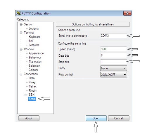
Now Open any one of above tool and configure it as:
- Set Serial Line (com1)
- SPEED (BAUD)=9600
- Data Bits=8
- Stop Bits-1
- Parity: None
Finally click on “open”
Now, press reset pin of Microcontroller-board and you will see the values in putty terminal that you have typed in: main() { block }
Next I will be trying to add a keyboard with atmega32 and will see the values in puttty………………..
Thanks……….. to you all……..
################ Rocks !!!##################
Source: MICROCONTROLLER to PC Communication Via PL2303 (USB TO UART TTL) Converter
- Why is a USB to UART converter needed for this project?
Modern computer systems often lack a native serial port (DB9), requiring a converter like the PL2303 to bridge the USB port to the RS232 interface. - Which specific USB to UART converter chip was selected for this project?
The PL2303 was chosen due to its availability and cost compared to other options like cp2102 or FT232RL. - What are the voltage levels defined by the RS232 standard for logical states?
A MARK/LOW signal represents a logical one using -3 V to -5 V, while a SPACE/HIGH signal represents a logical zero using +3 V to +5 V. - How many lines are minimally required for RS232 physical transmission?
Three lines are at least needed: RxD (Received data), TxD (Transmitted data), and GND. - What tools are required to compile and run the provided C code?
The project requires WinAvr 2008 and Cygwin, though the same code can also run on AVRStudio. - What configuration settings must be applied in the terminal software?
The terminal must be set to Serial Line com1, Speed (Baud) 9600, Data Bits 8, Stop Bits 1, and Parity None. - What function is used to initialize the UART in the provided code?
The function uart_init(unsigned int baud) is used to initialize the UART with a specific baud rate setting. - What happens when the microcontroller reset pin is pressed after uploading the code?
Pressing the reset pin causes the values typed in the main block to appear in the PuTTY terminal window.