
Summary of Minimalist Arduino using ATMega328P microcontroller
This article details the construction of a "Minimalist Arduino," an Arduino clone designed for permanent circuits on breadboards or PCBs. It includes only essential components: an ATMega328P microcontroller, an LM7805 voltage regulator, capacitors, resistors, and LEDs. The kit omits wires, jumpers, and reset switches to remain open-ended. Programming requires external tools like a USB-to-Serial FTDI converter or an ICSP programmer header, as no onboard communication interface is included.
Parts used in the Minimalist Arduino:
- LM7805 voltage regulator
- Two 10uF capacitors
- One 150 Ohm resistor
- One green 3mm LED (power supply)
- ATMega328P microcontroller
- One clock crystal
- Two 22pF capacitors
- One 10 kOhm resistor
- One 3mm Green LED (status)
- One 100nF capacitor
Overview
Here at the Transistor, we love the Arduino platform, so we decided to make our own Arduino Clone. The Minimalist Arduino is designed for use in permanent or custom circuits on solderless breadboards, stripboard, or custom PCBs. It contains only the bare minimum parts required for building the Arduino platform. The schematic for the board can be downloaded here (pdf). Please read all instructions on this page before assembly. The parts list is as follows, with linked manufacturer datasheets when available:
These parts consist of two main components: The power supply circuit, and the ATMega328P and supporting circuitry. The power supply circuit is made of of the LM7805 voltage regulator, (2)10uF capacitors, (1) 150 Ohm resistor and (1) green 3mm LED. Circuit power can be supplied using these components and a 7 to 18V input voltage, or via a separate regulated voltage source such as power over a USB to Serial FTDI converter. Only use one power source to drive the 328P chip, or you may damage it.
The remainder of the components are part of the ATMega328P circuit and support. This includes (1) clock crystal, (2) 22pF capacitors, (1) 10 kOhm resistor, (1) 3mm Green LED, (1) 150 Ohm Resistor, and (1) 100nF capacitor. The kit contains no wires, jumpers, or reset switch as the applications of this kit are intended to be open-ended and we did not wish to include unnecessary components.
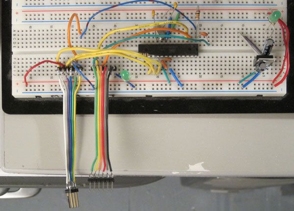
Communicating with the Minimalist Arduino
In order for this kit to be fully functional, you must have a means by which to program and communicate with it. We did not include any means to do this in the kit, though our schematic shows the two most common methods for programming or sommunicating with a standalone ATMega328P: A USB to Serial FTDI dongle, and an ICSP Programmer header pinout.
We recommend using the USB to Serial FTDI chip as the primary method of programming and communicating with the Minimalist Arduino in conjunction with the Arduino IDE. Note that the second 100nF capacitor is used on the reset line for this method. The USB to Serial FTDI converter you use may not require this capacitor to function properly. Be sure to check your documentation. There are many places which sell USB to Serial FTDI chips. We recommend the USB-BUB from Modern Device. They are also available from Sparkfun and probably many other locations which we have not used. Since this chip has a reset pin and will automatically reset the 328P when programming, there is no need to include a physical reset switch in this kit. Also, a single USB to Serial FTDI board will be able to program as many kits as you want, as long as continued serial communication with the board is not required.
For more detail: Minimalist Arduino using ATMega328P microcontroller
- What is the primary purpose of the Minimalist Arduino?
It is designed for use in permanent or custom circuits on solderless breadboards, stripboard, or custom PCBs. - Can I power the board using both a 7-18V input and a USB source simultaneously?
No, you must only use one power source to drive the 328P chip, or you may damage it. - Why are wires, jumpers, and a reset switch not included in the kit?
The applications are intended to be open-ended, so unnecessary components were excluded. - What is the recommended method for programming the chip?
The authors recommend using a USB to Serial FTDI chip in conjunction with the Arduino IDE. - Does the USB to Serial FTDI converter always require the second 100nF capacitor?
No, some converters may not require this capacitor, so you should check your specific documentation. - How does the USB to Serial FTDI handle the reset function?
The chip has a reset pin that automatically resets the 328P when programming, removing the need for a physical switch. - Is one USB to Serial FTDI board sufficient for multiple kits?
Yes, a single board can program as many kits as desired as long as continued serial communication is not required. - What voltage range is required for the input power supply?
Circuit power can be supplied using a 7 to 18V input voltage.
