Summary of MONITOR TEST CIRCUIT WITH ATMEGA88
This article describes a monitor test circuit utilizing an ATmega88 microcontroller to analyze audio output from a game and an older Atari amplifier. The project aims to verify the functionality of the audio signal path by monitoring the circuit's performance alongside standard game music.
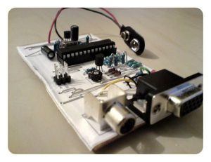
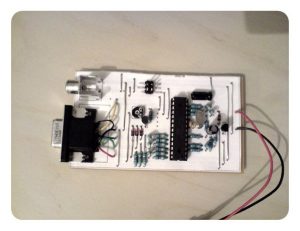
Parts used in the Monitor Test Circuit with ATmega88:
- ATmega88 microcontroller
- Old Atari amplifier
- Test circuit components
- Audio monitoring system
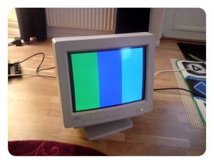
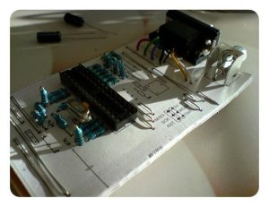
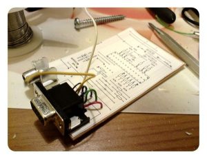
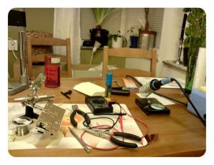
color image of a classic test circuit will monitor the audio output of this circuit in addition to the music in the game are from the old ateri amp could work in the test… Electronics Projects, Monitor Test Circuit with atmega88 “avr project, microcontroller projects, “
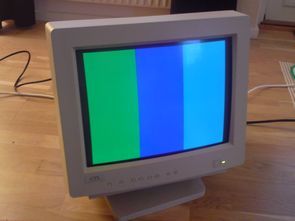
color image of a classic test circuit will monitor the audio output of this circuit in addition to the music in the game are from the old ateri amp could work in the test sample watch the video you’ll see 🙂
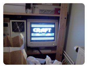
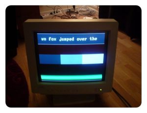
MONITOR TEST CIRCUIT WORK

Source: linusakesson.net Source2: MONITOR TEST CIRCUIT WITH ATMEGA88 Monitor Test Circuit with atmega88 alternative link: monitor-test-circuit-with-atmega88.rar
- What is the main purpose of this project?
The project uses a monitor test circuit with an ATmega88 to monitor the audio output of the circuit in addition to the music in the game. - Can the old Atari amp work in the test sample?
Yes, the old Atari amp could work in the test sample as described in the text. - Where can I find the source for this project?
The source is listed as linusakesson.net and an alternative link provides a rar file named monitor-test-circuit-with-atmega88.rar. - Does the circuit monitor game music?
Yes, the circuit monitors the audio output in addition to the music in the game. - Is there a video available to watch?
Yes, you are invited to watch the video to see the classic test circuit in action. - What type of microcontroller is used in this AVR project?
The project utilizes an ATmega88 microcontroller. - Are there multiple images provided for the circuit?
Yes, the article references a gallery containing multiple color images of the classic test circuit.