Introduction
For our final project we built a prototype of a circuit intended for a picosatellite that measures temperature and acceleration, sending the information wirelessly back to a base station receiver.
The N-Prize is an amateur rocketry competition challenging groups to launch a very small (10g-20g) satellite into orbit for less than $2000, and track it over 9 orbits. While modern large satellites require hundreds of people working together to build and are incredibly complicated, the N-Prize offers the opportunity for something dramatically different- a very small satellite, which can be built by one or two people. At its core, the only electrical components required are the power source and a transmitter. The only requirement for the prize is that the satellite can be tracked; like Sputnik, our satellite circuit prototype primarily consists of a transmitter beacon, and makes further use of the microcontroller to adequately sample the two onboard sensors.
High Level Design
Rationale
There’s nothing quite like space exploration to get the creative juices of an engineer flowing, and what better outlet than a final design project? The N-Prize fits this mold pretty well, it’s an amateur rocketry competition with an emphasis on low cost and easily accessible components. If a couple of college students can build a working satellite in a month, then so can anyone else. A 20 gram mass is sufficient to fit more than one integrated circuit along with connectors and a small power source. Furthermore, the task of building such a device is very feasible; all you need is an RF transmitter and a power source. Of course, such a seemingly simple task has many unexpected challenges to work out.
Logical Structure
Our satellite’s core feature is the RF transmission system and protocol. This is the most important for a simple reason: if you can’t hear (or see) your satellite, you can’t prove that it’s there, and it is of no use to you. Initially, we wanted to use our own protocol that would follow an existing communications standard such as HDLC, which is good for small packets and includes a CRC check code, but since there was already a convenient protocol written for the transmitter we had the easiest access to, the RCT-433, we elected to use it instead. Without Meghan Desai’s Wireless Protocol it is unlikely we would have succeeded in accomplishing the amount we did. As is, we integrated the existing functions, updated for the Mega-644 chip and GCC compiler, with an analog multiplexer to be able to read more than one sensor. We extended the protocol by providing an 8 bit cyclic redundancy check (CRC) code for error detection. On the receiver side, the frames are decoded using the aforementioned protocol, checked with the CRC, and output to a workstation using the internal UART on the microcontroller.
Hardware/Software Tradeoffs
Our project is all about trading hardware capabilities on a large satellite for an inferior but still sufficient solution on a small one. For one, any respectable large satellite would implement most of their electronics using multiple FPGAs or ASICs to give the engineers maximum control over the exact workings of the vehicle. Using only a single microcontroller to do both data input from sensors and data transmission turned out to be much more challenging than was expected, as the ADC operation interfered with the UART and prevented clean transmission when operated asynchronously. This was the most significant tradeoff we had to make, between using two microcontrollers to allow for easy input of analog values and figuring out how to run the UART and ADC synchronously. Since we had a cushion in our budget, we elected to go with two chips as this greatly simplified the code required.
Software and Hardware Design
Software
We approached the software design with simplicity and scalability in mind. Our design is essentially a basic telemetry system suitable for updating the user as to the status of the relevant sensors on their device. We found an excellent open source program for calculating CRCs written by Michael Barr available on netrino.com. We modified this code for a CRC-8 and included it on both the transmitter and receiver side. The ground station output is simply formatted text on a serial communications line hooked up to a computer. In a real ground station, the microcontroller would do no formatting and simply send a parsed binary stream, but as we had no software for analyzing this data and no need for it, we decided to do all our formatting before transmission.
On the isolated transmitting system we tried to utilize the hardware features of the 644 as much as possible so as to avoid messy code. Unfortunately, some of these features have idiosyncrasies that are more complicated than we were expecting and so maximum use of hardware features was bypassed in exchange for a quicker design. Specific issues we ran into include being able to reconfigure the internal UART on the fly to handle different baud rates of data, and running both the UART and ADC on the same chip in close timing. The former of these issues could be resolved, but the latter proved far more challenging than expected, and was bypassed in exchange for a hardware solution. A complete program listing follows:
Ground and Satellite
crc.c
//This file was written by Michael Barr and modified by us to perform CRC-8.
void crcInit(void);
This function initializes the look up table used in the crcFast function, allowing the calculations to be easily performed in real time. The generating polynomial is 0x07 and the initial remainder is 0xFF, in order to avoid issues with data that is all zero.
crc crcSlow(unsigned char const message[], int nBytes);
This function explicitly calculates the modulo-2 division required for a CRC and as such is much slower than the following one.
crc crcFast(unsigned char const message[], int nBytes);
This function uses the LUT generated by calling crcInit() to quickly find the CRC of the provided message.
txrx.c
//Written by Meghan Desai, modified for use with Mega-644 and GCC compiler.
//Only modified functions are listed.
void txrx_init(int tx, int rx, int baud_num, char led);
This function initializes either the transmitter, receiver, or both for the specified baud rate number as calculated per UART register specification. It has been modified so as to not actually start the transmitter when called, thereby saving power.
ISR (USART0_UDRE_vect)
The transmit ISR, this interrupt routine has been modified so as to shut down the transmitter once the last byte has been successfully sent over the UART.
void encode(void);
This important function encodes the data that has been loaded into the transmit buffer into the format required for successful RF transmission. It has been modified to read the code bytes from program memory, instead of simply from an array. This makes no functional difference and is probably unnecessary.
void tx_me(char tx_data[], int length, int id);
This function has been extensively modified to append a CRC to the data stream being sent, and correctly give the new length. After completing this task it then starts up the transmit ISR manually, as opposed to continual operation in the previous design.
Ground Station
Ground.c:
void initialize(void);
This function configures the ground station by initializing the uart, sending a startup message, configuring the LED port, starting a timer, initializing the crc, and finally initializing the uart (note that this overwrites the previous uart initialization) to receive the first frame.
ISR (TIMER0_COMPA_vect)
This ISR increments a 1ms timer. Currently this timer is not used for anything.
int main()
The main function decodes a complete frame into readable data, parses this data into a string for easy access, calculates the CRC check code for the received data and compares it to the expected value, briefly reinitializes the uart for transmission at 9600 baud, transmits a formatted string containing all important frame information, and reinitializes the receiver to catch the next frame.
Satellite
Satellite.c:
void init(void);
This function initializes the satellite transmitter unit. It configures ports A and C as inputs, port D as an output, timer0 for a 1ms timebase, the uart for 2000 baud transmission, and the crc.
void get_data(char count);
This function loads the data buffer with the packet count, 0xece476, a 16 bit time in milliseconds, and the contents of port A (temperature) and port C (acceleration).
ISR (TIMER0_COMPA_vect)
This ISR increments a 16 bit system time and decrements the timer used to trigger frames.
int main()
Every 100ms, the main function loads a frame into the data buffer, increments the packet count, transmits a frame, and toggles the led.
ADC
adc_tester.c:
void initialize(void);
This function initializes the ADC unit with ports B, C, and D as outputs. It configures timer 0 and the ADC, and starts the first conversion.
void task1(void);
This function calls the correct ADC read function and updates the corresponding port based on the value of the multiplexer selection variable. It updates the mux selection, on port D, and starts the next conversion.
void getTemp(void);
This function loads ADCH into the temperature variable and performs a brief conversion to degrees fahrenheit.
void getAccel(void);
This function loads ADCH into the acceleration variable, but does not perform a conversion.
ISR (TIMER0_COMPA_vect)
This function decrements the timer that controls when ADC reads are performed.
int main(void)
This function calls task1 every 10ms, updating the values output on ports B and C.
Hardware
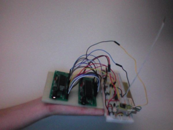
The hardware consists of the sensors multiplexed through to an MCU, which then sends the processed data in packets via a wireless link through a transmitter; the receiver on the other end of the link then feeds another MCU the packets, and the data is formatted and displayed to the user with the hyperterm interface.
Parts List:
| Part | Source | Cost |
| ATmega644 (x1) | Atmel (via Bruce Land) | $8 * 3 = $24 |
| custom PC board (x2) | Bruce Land | $4 * 2 = $8 |
| STK500 (x1) | Atmel (via Bruce Land) | $15 * 1 = $15 |
| 9V DC power source (x2) | Bruce Land | $5 * 2 = $10 |
| RCR-433 receiver (x1) | Radiotronix (via Bruce Land) | $4 * 1 = $4 |
| RCT-433 transmitter (x1) | Radiotronix (via Bruce Land) | $4 * 1 = $4 |
| bread-board (x2) | ECE 3150 Lab | free (got to keep them after the last lab) |
| DIP socket(x2) | Bruce Land | $0.50 * 2 = $1 |
| header pins (x77) | Bruce Land | $0.05 * 80 = $4 |
| MMA1220 accelerometer (x1) | FreeScale (via Bruce Land) | free, sample |
| CD4051 analog multiplexer (x1) | Analog Devices (via Bruce Land) | free, sample |
| LM34 temperature sensor (x1)) | Bruce Land | free, stocked |
| miscellaneous (resistors, capacitors, inductors, wiring) | Bruce Land | free, stocked |
Total = $70.00
For more detail: Multisensor Data Transmission Using Atmega32