Introduction
We have endeavored to develop a means by which eye gaze can be detected. This goal was achieved using the same principles learned in Lab4, where we recorded the motor speed of a small hub fan using the combination of IR emitter plus phototransistor, henceforth referred to as an emitter-phototransistor pair.
![]() High Level DesignSeveral approaches have been taken to implement eye tracking, the so called “bright pupil” and “dark pupil techniques” for those interested in consulting the literature. We are geared towards such a project for two reasons. First, this project draws on knowledge learned within both the biomedical and electrical & computer engineering disciplines, which pleases us being that we are biomedical engineers concentrating on bioinstrumentation. Secondly, it lends itself to many useful applications, which we will address later in this report.
High Level DesignSeveral approaches have been taken to implement eye tracking, the so called “bright pupil” and “dark pupil techniques” for those interested in consulting the literature. We are geared towards such a project for two reasons. First, this project draws on knowledge learned within both the biomedical and electrical & computer engineering disciplines, which pleases us being that we are biomedical engineers concentrating on bioinstrumentation. Secondly, it lends itself to many useful applications, which we will address later in this report.
The outcomes expected from this project rely on the wonderful properties of light. Specifically, we note that incoming light rays hitting an object will either be reflected or absorbed. The degree to which reflection and/or absorbance takes place depends on material properties of the object. Here within, our material of interest is a soft tissue, the eye. We focus on three parts of the eye that will respond to incoming light rays in a different manner: 1) the sclera (the white portion of the eye), 2) the iris (the region bearing one’s eye color), and 3) the pupil (the black entrance hole that serves as a light receptacle).
Though dissimilar from a microscopic cellular viewpoint, this is not of primary concern. Rather, interest lies in the clear color difference apparent in the three regions (mentioned above) that will have differing interactions with light. Just as we observed in Lab4, we expect a higher signal stemming from light directed to the pupil as compared to light directed toward the sclera. Nearly all the light directed toward the entrance pupil is absorbed. The white color of the eye reflects a majority of the light rays directed towards it. The ratio of light rays absorbed to reflected when directed to the iris depends on the eye color, with those eye colors darker in tone pigmentation yielding the higher signals.
Background Math
We note that the user’s focus is directed towards the Dell Monitor provided at each lab station in the Phillips 218 lab. At an estimated viewing distance of 20” (50.80cm), the Dell Monitor subtends 20.5 degree x 18 degrees of visual angle. Please use Figure 2 below for a visual depiction of this information [1].
(Note: Ideally, it would be nice to map 2-dimensional gaze to one point on the monitor. Due to the uniformity that exists within the three regions of the eye listed previously, this is not entire possible with the setup we have implemented. (Please see Footnote [1].)
The main loop will update the contents of the frame on the TV screen and read the signals from the ADC while the MCU is not sending data to the screen (Linecount 231 to Linecount 30). It first prints a cursor on the center of the screen to indicate the reference level. Whenever the difference between the updated signal and the reference is above the threshold, the MCU will update the position of the cursor according to the direction of the eye movement it detected.
Expected Results
Our initial goal was to detect movement in two dimensions, as shown in Figure 5. The expected results from the emitter-phototransistor pair indicated in the left-most column are shown in each row, for particular gaze (indicated by top-most row). Results obtained confirm expectations seen in the first two rows of this figure. (Please see “Results” section below) [2].
From these four cardinal detections, the next step would be to extend our detection into the ordinal directions. Figure 6 shows the expected results for gaze tracking in these ordinal directions.
Hardware/Software Tradeoffs
Real time eye/gaze tracking system is made possible with the incorporation of a CCD camera. The incorporation of a CCD camera adds an additional $20 expense to the budget. This is a significant addition in terms of budget costs. After some discussion, we decided that the incorporation of the CCD camera is well worth the cost. However, data collected from the CCD camera (i.e. frames of eye/gaze tracking footage) cannot be processed in real time with the Atmega 64 bit microcontroller. As such, we felt it more appropriate to use the emitter-phototransistor setup already being utilized. Though this is limiting, in the sense that one can only track eye movement in 8 directions (as opposed to “any” direction as would be the case with eye/gaze tracking with the CCD camera), there are benefits. As we have seen in Figure 5 (and Figure 6), our expected outcomes are much simpler in nature and much simpler to deal with. This simplicity helps to ensure that we have a device that responds to user input at near real time without adding too much strain on the microcontroller. This is a stepping stone that will serve the basis for future projects that will inevitably make improvements that strive for the goal of a “gaze tracking” system that can be achieved in real time with the resources used here or improved resources.
Standards
Safety. Given the nature of our backgrounds as biomedical engineers, our primary concern on any given project (health related or not) is safety. Specifically, is it safe to expose the eye to x amount of IR light over a finite amount of time, directed to the same area of soft tissue?
We first note that IR light is not visible light, but it resides after red light and opposite blue/ultraviolet light. It is known that a large percentage of IR light is transmitted through the skin (another type of soft tissue) [3]. The same result is expected for IR emission towards the eye. With ultraviolet light, however, the complete opposite is true. Blue light is absorbed by soft tissues and is known to cause damage to cells (specifically, damage to DNA). This is why the general populous is asked to be careful when exposed to sunlight for a long duration of time.
Freasier and Sliney have acknowledged that 0.3mW/cm2 is the maximum allowable intensity that the retina can be exposed to IR without damage. Being that our LTE-4208 device has a maximum aperture radiant incidence measure of 1.68mW/cm2, one must be careful in using this setup for long durations of time. [4] (Please see footnote).
National Television Systems Committee, NTSC. According to NTSC standards, television signal should contain information for starting a new frame, information for starting a new line, and information for brightness (white or black color pixel). As discussed in lecture, a long pulse (160–180 µs) near 0V is indicative of the start frame command. A short pulse (5 µs) near 0V is indicative of the start new line command. A voltage of 0.3V encodes a black pixel, a voltage of 1.1V encodes a white pixel, and in-between is grey [5]
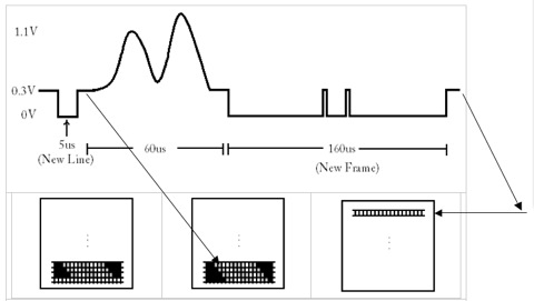
Figure 7. Diagram of video/sync signal coming from Port D.5 and D.6 of ATmega644. The 5µs pulse near 0V indicates the start of a new line. The lone 160 µs pulse with two intermediary spikes indicate the start of a new frame. (Technically, the bottom row of the left-most TV monitor image should be black pixels. To better display the idea of sync/video signal transmission, we have left it as white pixels. The next image (TV monitor in the center) shows the resulting brightness after the 60 us interval of video/sync signal information. The arrow here indicates that a new line has started.) (Further note that the new frame command could be in the range of 160—180µs)
Patents, copyrights, and trademarks which are relevant to your project.
Our project has been an attempt to think about the life of the future and to think of how technology can once again make people’s lives easier. There are several methods being employed for gaze detection/tracking. These methodologies, though, make use of a CCD camera, at the very minimum. We distinguish ourselves, though, by attempting such a feat without the use of such a camera [6].
Program/Hardware Design
Hardware
The hardware setup was quite simple. The hardware simply consisted of two pairs of emitter-phototransistor mounted atop goggles/glasses (in order to detect one-dimensional eye tracking). As noted before, the placement of these pairs is important [7]. Emitter-phototransistor pairs are placed off-axis so as to anticipate the arrival of the pupil upon the user shifting his/her gaze. The output signal stemming from the phototransistor is amplified for convenience. This way, it is easier to see the changes in signal brought about by different portions of the eye interacting with IR light. Amplification also makes it easier to set a threshold that will later be used for determining left vs right eye movement. The amplified signal is connected to Port A.0 and A.1, thus making use of the analog to digital (ADC) converter on the STK 500 board. Port B is jumpered to the LEDs as a means of visually displaying which direction the user is looking (i.e. toggling lights for a specific LED). This also served as a means for debugging. Lastly, we enabled hyperterm which was an invaluable addition to the hardware/software development process as it was continuously utilized for debugging and confirmation that things ought to be working the way that they were intended. (Assumption: User moves both eyes in the same direction at all times.)
Parts List:
| Parts | Source | Quantity | Unit Cost | Total |
| STK500 | ECE 4760 Lab | 1 | $15.00 | $15.00 |
| ATMega644 | ECE 4760 Lab | 1 | $8.00 | $8.00 |
| Op-Amps | ECE 4760 Lab | 2 | $0 | $0 |
| Safety Goggle | Previous Owned | 1 | $0 | $0 |
| IR Emitter |
ECE 4760 Lab | 2 | $0.25 | $0.50 |
| Phototransistor |
ECE 4760 Lab | 2 | $0.54 | $1.08 |
| Resistors & Capacitors | ECE 4760 Lab | — | — | $0 |
| Total | $24.58 |
For more detail: Optical eye tracking Using Atmega644