Abstract
Our project is a standalone temperature and fan monitoring and control unit for the PC. It uses the temperature readings to adjust fan speeds in order to regulate temperature and noise. The system is flexible in that it can be configured to be either completely autonomous, or set up to be configurable. It is also highly configurable in the setting up of the features and parameters. The entire unit is controlled by the 2 Atmel Mega32 MCUs – 1 for the main control unit and 1 for the RF remote control, with inputs to the ADC (for thermal sensors), port pins, RS232 serial connection and output to the LCD, port pins and RS232 serial connection. The RF remote control controls specific settings of the unit. The main unit is powered off a standard 4-pin PC Molex power connector while the remote control is powered off a 9V battery.
Introduction
Computer devices have steadily increased in transistor count and clock speed as dictated by Moore’s Law. Despite various attempts at reducing power consumption and dissipation, power budgets have increased steadily, and thermal output has also increased correspondingly. Over the past 2 decades, microchips have gone from requiring no cooling, to passive cooling with a heatsink only and subsequently to active cooling with a heatsink and fan. As thermal output continues to increase, exotic cooling techniques that require large and fast spinning fans will undoubtedly be required.

With such high spinning fans comes another problem of noise. There is typically a tradeoff between cooling performance and generated noise. PC enthusiasts often go to great lengths in order to achieve an acceptable balance. Traditional fan systems have dealt with this problem either with manually adjustable fan speeds by the user or automatically by the host CPU. The former requires user intervention, which is cumbersome and potentially unsafe, and the latter requires intervention by the host CPU, possibly slowing down the system and requiring system hardware and software support for temperature monitoring and control. Autonomous standalone units are available, but they are rare and very expensive. A DigiDoc 5+ 5.25″ front panel unit with similar features can cost over $50. We designed and build a flexible, inexpensive, microcontroller controlled standalone PC temperature monitoring and control unit that can either be run autonomously or configured manually.
System Overview
The system behaves in one of two modes – autonomous mode or manual mode. Mode selection can be done either via the pushbuttons, HyperTerminal commands or the with remote control.
Autonomous mode
In autonomous mode, the MCU monitors temperatures via the 2 LM34 temperature sensors, and determines the appropriate fan speed to spin the attached fans. Below a user configurable threshold temperature, the fans are disabled. Once the temperatures detected are above the threshold temperature, the fan speed will be ramped up linearly from not spinning to maximum fan speed at another set temperature. The fans stop spinning once the temperatures detected drop below the threshold temperature. If the temperatures continue to increase past a temperature limit, a corresponding alarm and LED is triggered, warning the user of high system temperature.
The speed of the fan can be varied with 2 methods, either by voltage regulation or PWM. With voltage regulation, the fan supply voltage is varied in the range of 7-12V. With PWM, the supply voltage is alternated between 0V and 12V with a varying duty cycle. Both methods achieve fan speed monitoring, but have their pros and cons. Voltage regulation is easy to implement and has few side effects, but since most fans only start spinning at ~7V, the minimum speed of the fan is limited to ~50% of the maximum speed. PWM has the advantage of a lower minimum speed of down to 10% of the maximum speed, as well as reduced power output and less voltage loss, but has the added complexity of requiring additional circuitry to retain the fan tachometer signal.
Manual mode
In manual mode, the user will have access to 2 potentiometers that vary the fan supply voltage to either fans independently. If the monitored temperatures exceed the maximum value, the alarm and corresponding LEDs are activated. In both modes, the monitored temperatures and the fan speeds(if supported) are output to the LCD for feedback. If supported, the system will also detect a locked fan rotor and activate a corresponding alarm and LED. The system parameters such as threshold/ maximum temperature and modes are user configurable via HyperTerminal. In addition, a remote control allows threshold temperature adjustments and mode switching.
High Level Design
The entire system consists of 2 units – the main control unit and the remote control. The high level block diagrams are shown below:
Main Unit
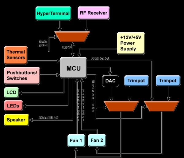 As the above block diagram shows, the main unit utilizes several of the MCU features learnt in class, including the I/O port pins, RS232 serial connection, the ADC(internal, not shown), LCD display, LED output, piezo speaker output and PWM output with varying duty cycle. In addition, a 4-bit R-2R DAC was built to control fan 1 via linear voltage regulation from 7-12V, and several switches were used to switch between inputs. For the switch between HyperTerminal and the RF receiver, we used a MAXIM MAX4053 triple analog mux to handle logic level signals, and for the switch between autonomous and user mode, we used two OMRON GE6 SPDT electromechanical relays to handle high current, +12V voltage sources.
Remote Control
The remote control is relatively simpler than the main control unit. It simply has an MCU on a protoboard, a RF transmitter into the RS232 port to wireless transmission of user input, buttons for user input, and LEDs for status display.
Parts list:
| Item | Unit Price | Quantity | Total Cost | Comments |
|---|---|---|---|---|
| Atmel MEGA32 MCU | $8 | 2 | $8 | Found one, priced one |
| Protoboard | $5 | 2 | $10 | |
| LCD display | $8 | 1 | $8 | |
| RS232 connector | $2 | 1 | $2 | |
| Radiotronix RF transmitter/receiver set | $8 | 1 | $8 | |
| MAX233ACPP | $0 | 1 | $0 | Sampled from MAXIM |
| MAX4053 triple 2:1 Analog MUX | $0 | 1 | $0 | Sampled from MAXIM |
| OMRON G6EK-134P-ST-US-DC12 SPDT relay | $0 | 2 | $0 | Sampled from OMRON |
| 4N35 optoisolator | $0 | 9 | $0 | Sampled from Fairchild Semiconductors |
| 3-pin fan connector | $0 | 2 | $0 | Found it |
| Breadboard | $0 | 2 | $0 | Had it |
| NS LM358 dual opamp | $0 | 1 | $0 | Had it |
| 5K trimpots | $0 | 2 | $0 | Had it |
| Resistors, Capacitors, Transistors, Diodes, LEDs LM34 |
$0 | Too Many! | $0 | Free lab parts |
| Total | $36 | Within Budget!!! | ||
For more detail: PC temperature control