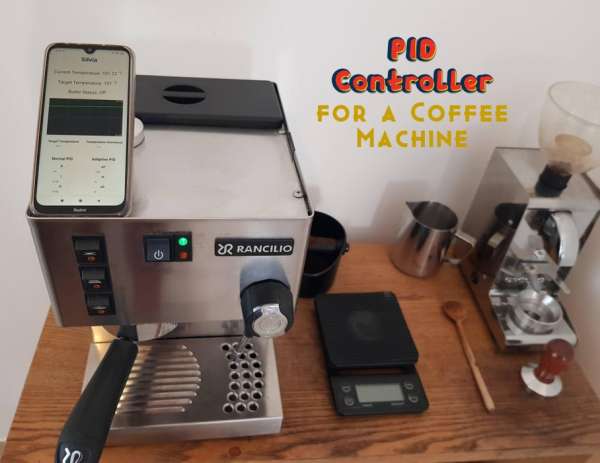
Summary of PID Controlled Thermostat Using ESP32 (Applied to a Rancilio Silvia Coffee Machine)
Summary: This project replaces the Rancilio Silvia brew thermostat with an ESP32-based PID controller using a PT100 sensor and MAX31865 to stabilize boiler temperature via a web UI, avoiding external boxes and keeping the machine restorable. It reads temperature in read-only mode first, then switches control to a 40A SSR driven by the ESP32 to switch the boiler, powered from the Silvia CPU unit. Software is uploaded via PlatformIO and served by the ESP32 for configuration and monitoring.
Parts used in the PID Controlled Thermostat Using ESP32:
- NodeMCU esp32 microcontroller
- Short micro USB cable (10cm - 15cm)
- Phone USB charger that can power the esp32
- 40A SSR
- PT100 temperature sensor with ring head
- MAX31865 Board
- Thermal paste
- 6.3mm spade connectors
- 16 AWG Gauge Wire
- 14 AWG Gauge Wire
- Heat Shrink
Warning
The Rancilio Silvia machine runs on high voltage. Any modification to it might be fatal to you or your machine, you act at your own risk and responsible for your modification. Any modification to the machine might void the manufacturer warranty. Make sure to disconnect the machine from the power line before working on it.
What is a PID controller?
A proportional-integral-derivative controller (or just PID controller) is used to regulate speed, temperature, pressure or other process variable with high accuracy and stable results. I am going to use the Arduino PID library to control the temperature of my Rancilio Silvia coffee machine. More mathematical information can be found on Wikipedia – https://en.wikipedia.org/wiki/PID_controller
Why would I modify my working espresso machine?
I bought my new Silvia E v5 in 2019 and it is still working as new, so why would I modify it? The Silvia has 3 thermostats in it:
- Brew thermostat 100°C (marked with red dot)
- Steam thermostat 140°C
- Safety thermostat (cuts the power if the boiler reaches 165°C)
Silvia’s original brew thermostat turns the boiler on at around 90°C and turns it off around 100°C. Once turned off, the temperature will continue to climb up to ~114°C and only then it starts to cool down. This means that every time you pour an espresso shot, the temperature will be different. These temperature variations make it very hard to get a good espresso shot at the right temperature, which has a huge effect on the taste. You can do temperature surfing or install a PID controller 🙂
Wait, but there are ready-to-use PID controllers online!
That’s right, but all the solutions I found online (well, except meCoffee.nl which are not available) require an ugly controller box outside the machine or cutting holes in the machine’s box. I wanted to keep my machine fully restorable to its original state.
So my controller will use a web UI to control the target temperature.
Also, learning new things and DIY is fun! This was my first microcontroller project.
Supplies:
Parts I used
- NodeMCU esp32 microcontroller
- Short micro USB cable (10cm – 15cm)
- Phone USB charger that can power the esp32
- 40A SSR
- PT100 temperature sensor with ring head
- MAX31865 Board here or here
- Thermal paste
- 6.3mm spade connectors
- 16 AWG Gauge Wire (will be used to turn on/off the SSR)
- 14 AWG Gauge Wire (will be used to connect the USB charger to the 220V power supply)
- Heat Shrink to cover the soldering
Tools needed
- Soldering Iron
- Small flat head screwdriver
Resources I used
- MAX31865 Board manual on Adafruit
- Avi Schneor’s Silvia mega mod – how to disassemble and general information about the machine.
- Parts of the code and concepts from here
- Idea about the CPU connections of Silvia (it’s in German but you can use Google translate)
Step 1: Connecting the Sensor to the Board
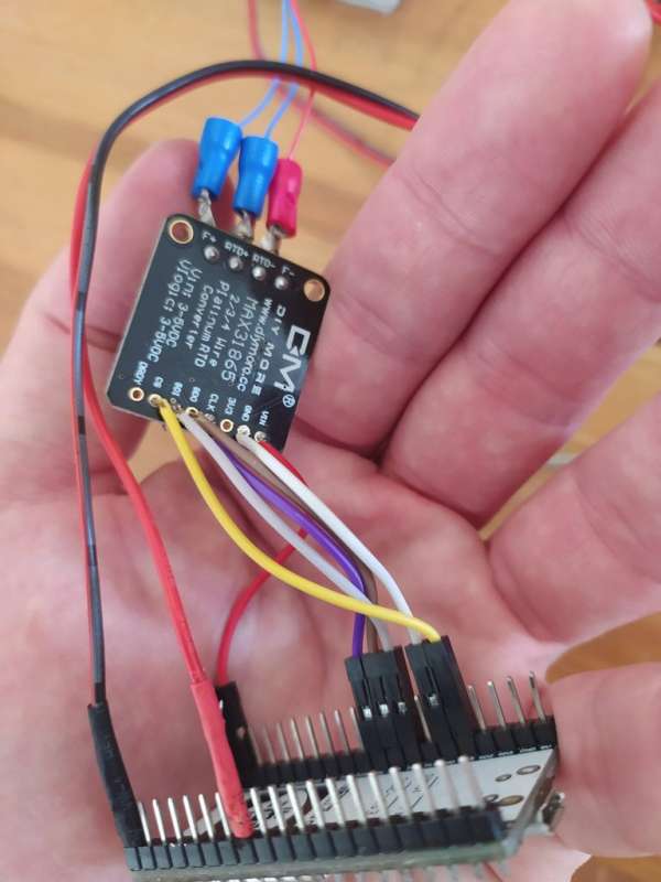
- Prepare the MAX31865 board based on the instructions found here – https://learn.adafruit.com/adafruit-max31865-rtd-pt100-amplifier
Each PT100 sensor might have a different configuration using this board. - Connect the PT100 sensor to the MAX31865 board and the MAX31865 to the esp32 board.
I used the following pins on the esp32:
MAX31865 pin > Esp32 pin
CS > 13
DI > 14
DO > 27
CLK > 26
VIN > 3.3V
GND > GND
Step 2: The Software
I have used PlatformIO on Visual Studio Code so it would be very simple to install all the required libraries.
I have also used some code parts from https://github.com/Schm1tz1/ESPressIoT which was a great source.
You can download or clone the code from GitHub – https://github.com/bnayalivne/silvia-pid
Make sure to edit the src/web.cpp file and change the ssid and password for the network connection.
To upload the software you have to do 2 things.
- Upload the data/ folder which contains the HTML/JS files – In VS Code click on the PlatformIO icon on the left find the “Upload File System image” task.
- Upload the software using “Upload” or “Upload and monitor” tasks.
Once the software is installed on the esp32 board you should get the IP address from the board on the IDE monitor.
If you open the IP address on your browser (for example http://192.168.0.123 ) you should see the UI of the controller showing the current temperature of the room.
Step 3: Preparing the Wires
Other than controlling the temperature using PID, I also wanted to have the following features:
- The controller has to turn on when Silvia is on, and turn off with the machine.
- No external power cables.
- It should be possible to undo any change easily (that’s why it was important to use the spade-connectors).
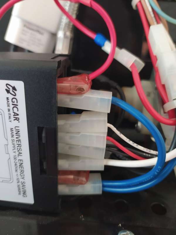
So I used the power going out from Silvia’s CPU unit.
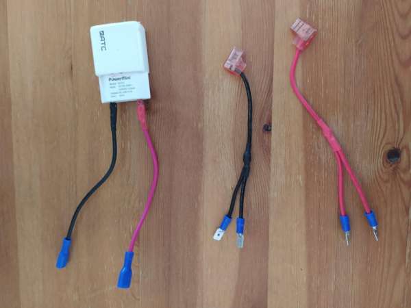
I have soldered female spade connectors to the USB charger,
And 2xCable splitters to take power from the original machine CPU unit.
I have also prepared red+black 14AWG cables with male spade connectors on one side to go from the SSR to replace the current thermostat.
Step 4: Connect As Read Only
On this step we are going to connect the temperature sensor as “read only” mode, to make sure we are getting correct temperature reading from the sensor before letting the new PID to control the boiler status.
- Connect the controller to the power supply – On the Silvia’s CPU unit I have disconnected cables 10 and 2 and instead connected my splitters, one leg of the splitter will connect to the original cable and the second will connect to the USB charger
- Connect the microUSB cable to the charger and pass it through the cables hole to the boiler area.
- I have used a small candy box (Altoids) to cover the esp32 and the MAX31865 boards.
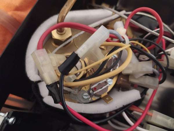
- Unscrew one of the brew thermostats (the one with the red dot on it, see image). screws and place the PT100 ring on it with some thermal paste. This will capture the boiler’s temperature and will be used in the PID software.
It’s time to make sure we are getting readings from the temperature sensor to the controller and that you are able to connect the UI from your phone/pc using it’s IP address. Make sure the controller turns on/off with the machine and that the temperatures match the boiler status (during espresso brew, during steam mode, etc…).
Do not proceed to the next step if you can’t get correct readings at this step.
Be careful not to turn on the machine while the covers are open, keep in mind that this is an high-voltage machine!
Step 5: Move the Control Over to the PID Controller
- Remove the 2 connectors from the brew thermostat and connect them with the red and black cables that will go to the SSR.
- Position the SSR unit behind the front cover. Make sure it’s away from the drip tray.
There is a single screw there that I used to fix it, but you mght want to drill another screw. - Connect the cables that go from the boiler (the cables that are now attached to the old thermostat cables) to the SSR AC side.
- Connect the DC side of the SSR to ESP32 board pins 19 and GND. This will make the SSR turn on/off on the AC side.
Source: PID Controlled Thermostat Using ESP32 (Applied to a Rancilio Silvia Coffee Machine)
- What is the purpose of adding a PID controller to the Rancilio Silvia?
To regulate the boiler temperature more accurately and avoid large temperature swings caused by the stock thermostat, improving shot temperature stability. - Which sensor is used to measure boiler temperature?
A PT100 temperature sensor with a ring head is used, attached to the brew thermostat location with thermal paste. - How is the PT100 sensor connected to the microcontroller?
The PT100 connects to a MAX31865 board which is wired to the esp32 using CS 13, DI 14, DO 27, CLK 26, VIN 3.3V, and GND. - How does the controller switch the boiler on and off?
An SSR (40A) is used; its AC side replaces the brew thermostat wiring and its DC side is driven by ESP32 pin 19 and GND. - How is the esp32 powered without external cables?
The project uses the Silvia CPU unit power via splitters and soldered spade connectors to power a phone USB charger that feeds the esp32. - What software setup is required for the esp32?
Use PlatformIO in VS Code, install required libraries, edit src/web.cpp for Wi-Fi credentials, upload the data/ folder as a file system image, then upload the firmware. - How can I verify the temperature readings before enabling PID control?
Connect the sensor in read-only mode, power the controller, access the ESP32 web UI via its IP, and confirm readings match boiler status during brew and steam modes. - Do I need to modify the machine permanently to install this system?
The design uses spade connectors and internal wiring so it is intended to be fully restorable without cutting holes or adding external boxes. - Where should the SSR be mounted?
The SSR is positioned behind the front cover away from the drip tray and fixed with an existing screw or an additional screw if desired. - What precautions are emphasized for this modification?
Disconnect power before working, do not run the machine with covers open, and be aware that modifications may void warranty and pose high-voltage risks.