Summary of Playing Simon On A Hacked Farm Toy
This article details a DIY project where the author repurposes a noisy plastic farm toy into an electronic Simon memory game using an Atmel Attiny2313 microcontroller. The hack involves installing ultrabright LEDs, modifying switch circuits with resistors, and adding a slide switch to toggle between original farm sounds and the new game mode. The software implements a finite state machine with speed increases and sound truncation tricks to ensure smooth gameplay.
Parts used in the Playing Simon On A Hacked Farm Toy:
- Plastic farm toy
- Atmel Attiny2313 microcontroller
- 3x AA batteries
- Ultrabright LEDs (Blue, Green, Yellow, Red)
- Slide switch
- 6 SPST switches
- 10 kΩ series resistors
- 100 kΩ pulldown resistors
- 22 Ω resistor for blue LED
- 56 Ω resistor for green and yellow LEDs
- 68 Ω resistor for red LED
- USBasp programmer or DB9 bit banging programmer
About
My kids have a plastic farm toy. It neighs, it baas, and frankly, it grates. But since I tricked it out with a microcontroller brain, at least it can play Simon.
One of the marvels of parenthood is the sheer volume of noisy plastic junk that gets thrown your kids’ way. It makes tremendous hacking fodder. For a while I had been watching to see if either of my daughters still expressed any interest in this moo-ing, oinking, polyethylene monstrosity. When the moment was right I grabbed it for re-purposing.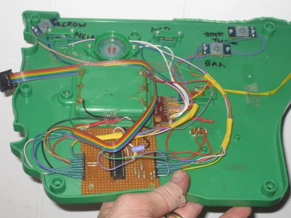
Grown up children of a certain age may recall a disc shaped memory game with the anthropomorphic name. Yes, I’m talking about Simon, from MB Electronics. In fact this evergreen toy never went away, and it has been recreated over and over in many different forms.
Getting a microcontroller to play Simon is, well, simple — as you might expect, given that the original game was programmed on a 4 bit chip with just 8192 bits of ROM. It helps that enthusiasts have catalogued everything about Simon that you could possibly want to know.
I chose to use the Atmel Attiny2313. This low cost chip had plenty of IO pins so that no multiplexing would be necessary. The code would easily fit in its 2K of flash memory, and 256 bytes of RAM could store enough moves for the most elephantine of memories.
Bastardizing the hardware
Hacking the toy was child’s play. There was masses of room inside the base to work with. 3x AA batteries provided 4.5 V supply for a PCB with a blob on that made all the noises. The PCB had connections for 6 switches that triggered the noises. The switches were SPST and the corresponding noise inputs were all active high. I connected the switches to the microcontroller input pins via 10 kΩ series resistors with 100 kΩ pulldown resistors. I also chose 10 kΩ series resistors between the output pins and the noise-sensing inputs on the blob.
To add a bit of bling I tricked out the animal stalls with ultrabright LEDs. I sized the series resistors to for 30 mA current based on the forward voltage of the LEDs and the expected sag of the Attiny output. After a bit of experimentation, fitting different values of resistor into an 8 pin DIP socket, I settled on 22 Ω for the blue LED (3.6 V), 56 Ω for the green and yellow LEDs (2.1 V), and 68 Ω for the red LED (2.0 V). These values gave LED outputs of roughly equal intensity.
I added a second slide switch to select between the original press-button-make-noise farm toy mode and the new Simon game. The farm mode turned out to be a useful debug setting to test each switch and the associated LED and animal noise.
Software implementation
The software retains the main features of the game, although there are a few adaptations:
- No multiplayer games
- Speed increases after 8, 14, and 20 moves instead of preset skill levels
- Much slower display of the move sequence initially so that complete animal noises are heard
- Extra time for user input to reach the various switches
The game was realized as a Finite State Machine. In START_SIMON mode the microcontroller initializes the random move vector. Next is LISTEN mode in which the sequence is displayed. REPEAT mode follows which seeks input from the user by way of the switches. Incorrect responses lead to LOSE mode. Correct responses lead back to LISTEN mode with a longer sequence unless the maximum length sequence is reached, in which case WIN mode follows. WIN and LOSE modes both lead back to START_SIMON mode. Moving the slide switch in REPEAT mode leads back to FARM mode.
Interrupt-based timing routines were used to debounce the switches and implement delays of various kinds. The microcontroller was allowed to idle between interrupts, thereby saving power. Pin change interrupts were used in preference to polling the switches. Pseudorandom sequences of moves were generated using a Galois Linear Feedback Shift Register.
Making the noises involved a bit of trickery. The animal noises were too long for quick play and needed to be truncated. The animal noise could be curtailed by sounding a different animal noise while the first noise was still sounding. The problem arose when sounding the same noise twice in a row. This was done by sounding a different intermediate noise very quickly.
Programming the Attiny2313
All the code, plus additional documentation such as the schematic, is located in a github repository. The firmware uses the default fuse settings and the code has already been compiled. All that needs to be done is to upload the hex files onto the chip.
You will need some method of programming the AVR chip. USBasp programmers can be found on ebay for less than $5: I used a DIY version. Another option if your computer has a serial port is to make a simple bit banging programmer built into a DB9 connector. I didn’t put an ISP header on the microcontroller board but it is easy enough to program the attiny2313 on a breadboard.
Once your target board is set up just type this into the command line, substituting the name of your programmer and its port location as appropriate:
avrdude -c usbasp -p t2313 -P com16 -U flash:w:simon1-attiny2313.hex
Construction Tips
This should be an easy hack. But don’t hot glue the LEDs in place like I did — if they burn out you’ll have a tough time rewiring. Also I had to chop away the lip of the base to get it to fit back on flush. 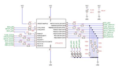
For more detail: Playing Simon On A Hacked Farm Toy
- Why did the author choose the Atmel Attiny2313?
The chip has enough IO pins to avoid multiplexing, sufficient flash memory for the code, and ample RAM to store move sequences. - How were the LED current values determined?
The author sized resistors based on the forward voltage of each LED color and the expected sag of the Attiny output to achieve roughly equal intensity. - What changes were made to the standard Simon game rules?
The modified version removes multiplayer options, increases speed after specific move counts, slows the initial sequence display, and adds extra time for user input. - How does the software handle long animal noises during gameplay?
Noises are truncated by sounding a different animal noise while the first is still playing, or inserting a quick intermediate noise if the same sound repeats. - What method was used to debounce the switches?
Interrupt-based timing routines were utilized to debounce switches and implement delays, with pin change interrupts preferred over polling. - How can a user select between the farm toy mode and the Simon game?
A second slide switch was added to toggle between the original press-button-make-noise mode and the new Simon game mode. - What programming tool is recommended for uploading the firmware?
A USBasp programmer or a simple bit banging programmer built into a DB9 connector can be used to upload the hex files. - Where can the full code and schematic be found?
All code and documentation are located in a github repository mentioned in the article.