Summary of Portable Solar Auto Tracking System
This article details a DIY portable single-axis solar tracking system built using aluminum T-slot extrusion, wheels, and a 12V linear actuator. The project enables a solar panel to automatically follow the sun from East to West for increased efficiency, featuring manual inclination adjustment and a CPVC-mounted sensor. It is designed for off-grid use with batteries and inverters, offering a cost-effective alternative to commercial trackers.
Parts used in the Portable Solar Tracking System:
- 50 watt solar panel
- 36 inch aluminum T-slot extrusion 1x1
- 24 inch aluminum T-slot extrusion 1x2
- Two 10 inch aluminum T-slot extrusions 1x1
- Two 8 inch lawn mower wheels
- Three 5 hole T joining plates
- Screws with t-nuts (1/4-20 x 1/2 inch)
- 180 degree pivot bracket
- Two 90 degree nubs
- 12 vdc linear actuator with 12 inch stroke
- Home CSP solar tracker
- 36 inch length of 1/2-20 all thread
- Lock nuts, washers, and nuts (1/2-20)
- 3 hole joining strip
- 36 inch length of 1/2 cpvc pipe
- Junction box of CPVC
- CAT 5 cable or light gauge stranded copper wire
- Anderson quick connectors
- Solar charge controller
Medomyself is a participant in the Amazon Services LLC Associates Program, an affiliate advertising program designed to provide a means for sites to earn advertising fees by advertising and linking to amazon.com
by: Dave Weaver
This build is made with aluminum t-slot extrusion. I chose that material because it is clean, light and great to work with. This could very easily be built with wood but it would not be quite so resistant to UV light and moisture. If you want to see more info on my solar builds than please subscribe to: http://medomyself.com/wordpress/
As long as the earth rotates the Sun will track the sky from East to West. Considering that a solar panel is only producing it’s maximum rated output when it is at right angles to the Sun it stands to reason that those same panels are only producing max power for a very brief portion of the day. These same panels, if turned every few minutes would be much more efficient.
I have been searching for years for a practical and cost effective auto-tracking solar panel but they are not really out there. The ones that do exist are not portable and they are very expensive. So I decided to build my own.
The system I built is a single axis system constructed with T-slot aluminum extrusion, a sturdy set of wheels, a 12 vdc actuator and a manually adjusted inclination. A 50 watt solar panel was used but it can handle up to 100 watts with modifications to the design. It has a solar charge controller, an affordable solar tracking component and an actuator to pivot the solar panel. Simply connect a storage battery to the quick-connect wires and charge your storage battery. If you only require DC power and you happen to use only LEDS to provide light through the evening you would have all that you need. However, most active folks require AC power for radios, TVs, coffee pots and perhaps even a refrigerator. In this case you will want to purchase additional batteries to create an array and connect them to a descent power inverter. Or, you can purchase any number of portable power packs on the market that will combine them in a nice compact and light-weight assembly. The Goal Zero is the ideal power pack for this system.
Materials List:
(1) 50 watt solar panel
(1) 36″ aluminum T-slot extrusion 1″ x 1″
(1) 24″ aluminum T-slot extrusion 1″ x 2″
(2) 10″ aluminum T-slot extrusion 1″ x 1″
(2) 8″ lawn mower wheels
(3) 5 hole T joining plate
(2) Bags 1/4-20 x 1/2″ screw w/ t-nut
(1) 180 deg. pivot bracket
(2) 90 deg. nubs
(1) linear actuator 12 v dc w/ 12″ stroke
(1) solar tracker Home CSP
(1) 36″ length of 1/2-20 all thread
(2) 1/2-20 lock nuts
(2) 1/2″ SS washers
(1) bag of (10) 1/2-20 nuts
(1) 3 hole joining strip
(1) 36″ length of 1/2 cpvc
(1) “J” box of CPVC
36″ of CAT 5 cable or any light gauge 4 stranded copper wire
Tools required
(1) 11/64 drill bit
(1) 1/4-20 tap
1/4-20 hand tap
3/16″ T – wrench
crescent wrench
wire strippers
wire nuts
electrical tape
more details medomyself.com
Step 1: Assembling the Mast to the Base
The first step is to mount the mast with the base. The mast is 36″ @ 1″ x 1″ T-slot extrusion. The base is 24″ @ 1″ x 2″ T-slot extrusion. They are connected together with a 5 hole bracket, also manufactured by 80/20.
Place (4) 1/4-20 screws into the bottom row of the 5 hole bracket, and (3) screws with t-nuts on the top row of the same bracket. Do not tighten yet. Slide the 3 holed side of the bracket onto the mast. Slide the 4 hole side of the bracket into base. Position the bracket so it is in the middle. Tighten the 4 screws on the bottom and then seat the mast firmly down against the base with your T wrench. Tighten the 3 remaining screws.
Step 2: Installing Axle Through Base
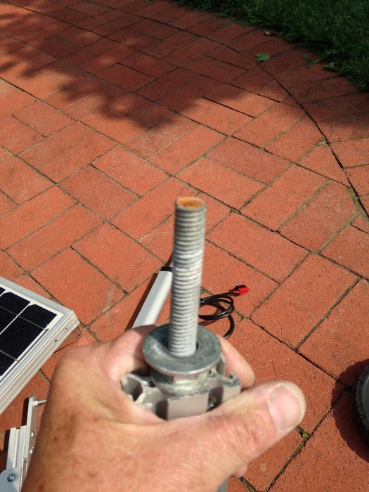
Now take the section of all-thread and place it through the center hole of the base. You will need approximately 4″ extending from each end to allow for the wheels to have enough clearance. Place a 1/2 washer on each end and then thread on a 1/2-20 nut on each end. Tighten them fully.
Now take a wheel and place it on the end of the axle as shown. Thread on a 1/2-20 lock nut on each end. This is not a Ferrari, the wheels should have a little play and they should spin freely.
This completes the base.
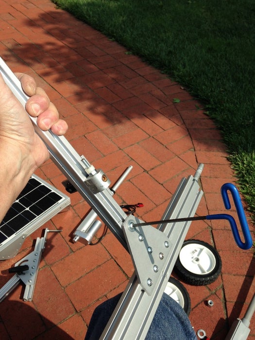
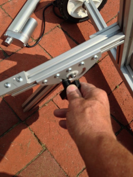
Step 3: Installing the Actuator Arm and Foot
The bottom portion of the mount is made up of (2) 10″ sections of 1″ x 1″ extrusion. One section is connected to the mast, the other is mounted on the 180″ pivot bracket and serves as a leg. This is where you will adjust the inclination.
The T bracket shown in the photo is no longer used, instead I use a 5 hole T bracket (same ones that will be mounted to the solar panel). Install screws and t-nuts on the bracket and slide down the mast as shown, approximately 10″ off the ground. Tighten the 3 screw on the mast side. Now slide (1) of the 10″ sections of 1″ x 1″ onto the (2) hole side of the bracket and tighten.
Take the remaining 10″ section of extrusion and install the 180 degree pivot bracket as shown. The turn knob and carriage bolt must be disassembled prior to installing. The 10″ section for the leg needs to be tapped on one end only. The 90 degree nub threads into the tapped section of extrusion.
Step 4: Installing Brackets for Solar Panel
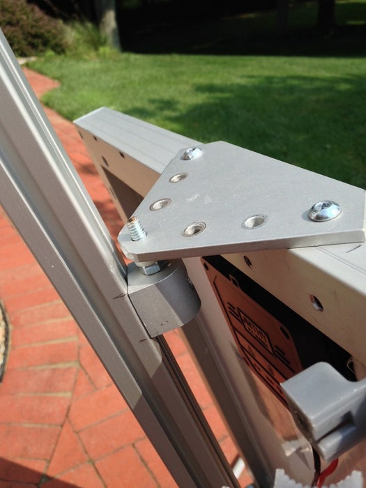
This step requires you to drill holes in the outside frame of the solar panel. Place one of the 5 hole brackets on the top of the solar panel and mark where the holes are going, this should be in the middle of the panel. Do this for the bottom also. Drill (2) holes, the 2 outside holes, with an 11/64″ drill bit. After the holes are drilled swap out the bit with the 1/4-20 tap and tap the holes. You will not need lubricant for these taps.
Take the (2) remaining 90 degree nubs and install them on the mast as shown. These should be spaced to match the distance between the two brackets. At this point you have two options, you can insert one of the 1/4-20 hex head screws into the solar panel bracket and into the nub. You can do this for the top and bottom. The alternative is to thread 2 small sections of 1/4-20 all-thread, about 1.5″ long with lock nut a plastic spacer into the nub. This allows you to slip the panel on and off easily.
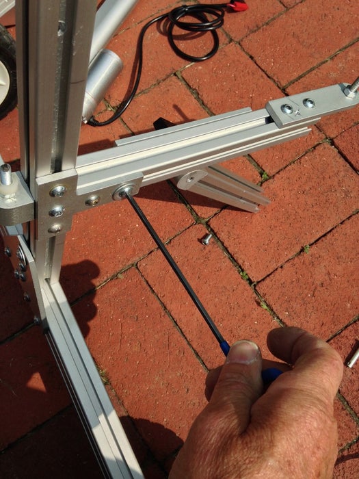
Step 5: Installing the Actuator and Hardware
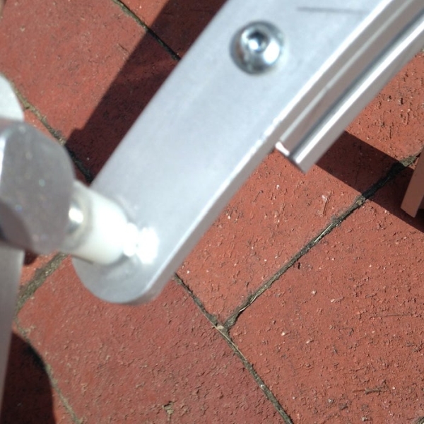
Now install the 3 hole joining strip at the end of the 10″ extrusion that extends from the mast. Install 2 button head screws and 2 t-nuts to secure it but leave the last hole vacant.
The actuator comes with mounting hardware. The angled cylinder bracket should be installed on the left side of the solar panel as shown using the same techniques for the solar panel brackets. One end has a wing nut and the other end is pinned.
Take a 2″ long 1/4-20 bolt and pass it through the vacant hole on the joining strip and thread on a 1/4-20 nut to secure it. Place a nylon 1/4″ tall spacer on the bolt,this will cut down on friction. Now thread on the the 1/4-20 wing nut on the bolt to secure actuator on one end. Install the actuator bracket on the solar panel and pin the travel rd of the actuator.
The actuator must not bind and it must travel the full arc. This will be tested later.
Step 6: Installing the Solar Tracker and Junction Box
The sensor is mounted on the end of the 1/2″ CPVC pipe. The sensor has (4) wires, battery plus, battery minus, CW & CCW for the actuator. The small junction box is mounted 3/4 of the way down the CPVC and another short section of CPVC extends out the bottom of the junction box, enough to reach to the bottom of the solar panel outer frame. This assembly is secured to the solar panel using pipe clamps. The wires will enter from the bottom and exit out the side to the controller and to the top into the sensor.
The solar tracker I used is manufactured by Home CSP. I have used the Tiny Tracker with all of the systems I have built and I have never had a problem. I certainly recommend using one for your system.
Step 7: Wiring the Components
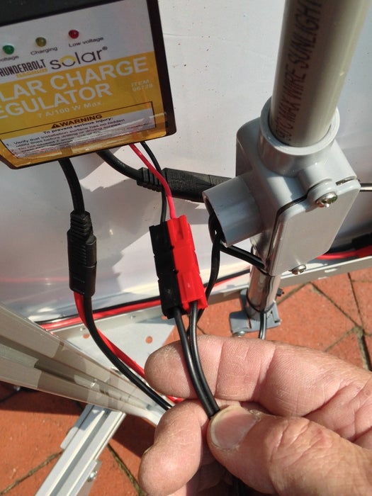
As for wiring your solar tracker you have a couple options. If you are using a 50 watt solar panel and your intent is to charge a large deep cycle storage battery that is in a power pack like Xantrex or by itself then simply connect as shown.
Anderson quick connectors are used to connect everything. Because this is only a 50 watt solar panel it does not produce very much current (< 3 amps), so a small 7 amp charge controller will be just fine. I chose to install this on the back of the solar panel with silicon but it would be better to use the charge controller that is built into some of the more common power packs.
Step 8: Final Preparation and Test
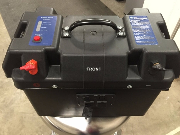
The power pack in the photo is just something I put together. I wanted a much lighter power pack that could be daisy-chained with other battery packs to increase the storage capacity. I used a battery box with an LED charge indicator. Instead of using a heavy lead acid battery I used a LiFePO4 20 AH battery. I put an 800 watt modified power inverter in the bottom with a remote control mounted on the front of the box. It only weighs about 15 pounds.
In the adjacent photo you will notice that I am using a 12 vdc cigarette power socket to convert to the anderson connectors. I also use a “Watts Up” meter to measure the charging current…nice to have.
When power is first applied the actuator will jog West then East and stop, after a few moments it will start to seek the Sun. From that point on the tracker will sample the light every 3 minutes or so. This process will repeat itself until sunset. At night it will go back to the East and set.
Install the long turn-knob w/ 1/4-20 stud. You will need to tap the end of the mast to install this.
Test Travel Of Actuator
This mount has no limit switches, the linear actuator has them built in, that is why you must ensure that the solar panel can travel about 180 degrees from East to West when facing due South. If the panel binds or does not travel enough loosen the 1/4-20 hex head screws that hold the 3 hole joiner strip and slide in or out to increase or decrease the travel. Retighten.
Step 9: Operation
Operation
The bottom leg of the mount needs to be folded out of the way for safe transport. To do this loosen the black turn-knob and fold the 10″ bottom leg flat toward the mast. Re-tighten the knob.
Move the solar mount to an area with a clear view of the southern sky. Position the handle on the mast so that it is facing due south. Connect the power pack to the solar mount.
Loosen the bottom turn knob and tilt the mount to match the Sun’s approximate angle. Tighten knob. Soon your panel will start to track on it’s own.
For more details and other builds:
https://www.etsy.com/shop/BuildFromPlans
http://medomyself.com/wordpress/
Attention – Coming in Jan. 2016 – Portable Solar Tracking Mount
In the first week of January 2016 we will be introducing a
complete solar tracking system for those of you that don’t want to mess with building one from scratch. We will be launching a single axis solar tracker that will handle a solar panel up to 100 watts. It will include:
50 watt solar panel
Solar Charge Controller
12 vdc actuator
Solar Tracker
Universal mount (handle up to 100 watt panels)
Wheeled portable dolly
Auto Single axis (azimuth)
Mechanical (inclination)
Source: Portable Solar Auto Tracking System
- Why was aluminum T-slot extrusion chosen for this build?
It was selected because it is clean, light, great to work with, and resistant to UV light and moisture. - How does the system improve solar panel efficiency?
The system tracks the sun from East to West every few minutes, ensuring the panel stays at right angles to the sun for maximum power output. - What is the maximum wattage this design can handle?
The original build uses a 50 watt panel but can handle up to 100 watts with modifications to the design. - Can this system provide AC power for appliances?
Yes, by connecting additional batteries to a power inverter or using a portable power pack like Goal Zero. - How often does the tracker sample the light?
The tracker samples the light approximately every 3 minutes after the initial seek phase. - What happens to the tracker at night?
At night, the tracker returns to the East position and sets until sunrise. - How do you adjust the inclination of the mount?
Inclination is manually adjusted using a turn knob on the 180 degree pivot bracket located on the bottom leg. - What type of battery is recommended for a lightweight setup?
A LiFePO4 20 AH battery is suggested to keep the total weight down compared to heavy lead acid batteries.