Summary of PROGRAMMED DOOR ALARM CIRCUIT ATTINY24 ATTINY13 CONTROLLED
This article details a low-power mini-burglar alarm system built around the ATtiny13 microcontroller, featuring IR remote control via an ATtiny13 or ATtiny24 transmitter. The device utilizes a reed switch for intrusion detection and supports deep sleep modes to achieve 30 μA power consumption. It includes features for arming/disarming, keychain programming, and optional SMS integration.
Parts used in the Mini-Burglar Alarm System:
- ATtiny13 microcontroller
- TSOP1736 IR receiver
- Reed switch
- BC847 transistor (or CT 315)
- Two CR-type lithium-ion batteries
- ATtiny24 microcontroller (for multichannel transmitter)
- Passive components
- Jumper JP1
- Jumper JP2
- Green LED
- Red LED
This simple mini-burglar alarm on the ATtiny 13 microcontroller is designed to protect apartments, offices, summer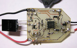 cottages … When the reed switch opens, the alarm beeps or, with a little refinement, you can send an SMS from a mobile phone. The alarm control is carried out by IR remote controls. Main features: dynamic power supply of the photo-receiver, wake-up from the “SLEEP” mode by interruption from the watchdog timer in the “POWER-DOWN” mode, and as a result low power consumption – about 30 μA.
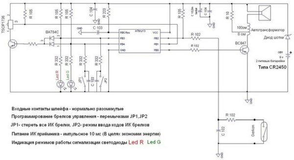
The schematic diagram of the device is quite simple. IR receiver – TSOP1736. The heart of the device is the ATtiny13 microcontroller. When the reed switch contacts open, an alarm is triggered. Schematic diagram of the burglar alarm (click on the diagram to enlarge):
The assembled device looks like this:
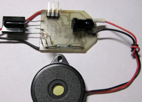

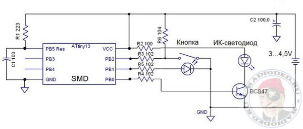
The infrared transmitter for controlling the alarm system is assembled on the ATtiny13 microcontroller and a dozen passive components. Instead of the BC847 transistor, you can use any low-power transistor, for example, a CT 315. The power source is two CR-type lithium-ion batteries. Schematic diagram of the infrared remote control to control the alarm system (installation of security / disarming):
Assembled keychain control:

When using a multichannel (99 channel) IR transmitter on the ATtiny24 microcontroller, you can use a large number of nearby alarms at the same time, controlling them by choice. Schematic diagram of the multichannel IR transmitter:
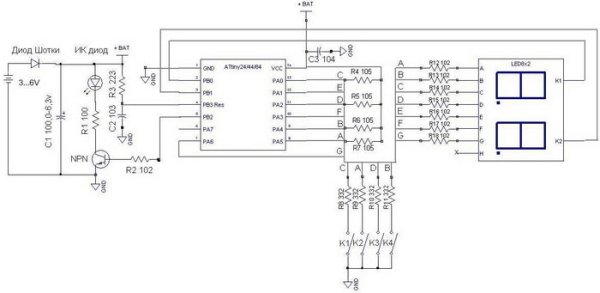
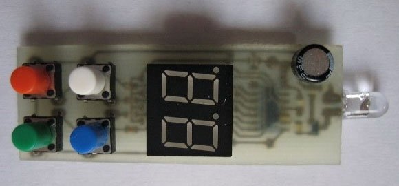
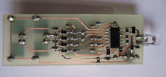
Assembled multichannel IR transmitter:
Alarm programming
Erasing all key chains
A beep will sound, the indicator continuously flashes in red 0.5 Hz
Adding new key chains
The indicator flashes continuously in green 0.5 Hz.
In confirmation of the recording keychain beep beeps 1 time.
If the keyfob memory is full, the indicator continuously flashes red with 0.5 Hz.
Work with the device
Arming with the door closed
The indicator flashes red with a frequency of 1 Hz.
Arming with the door open
The indicator alternately flashes red and green with a frequency of 1 Hz.
After closing the door, the indicator flashes in red with a frequency of 1 Hz.
Disarm
The indicator flashes green with a frequency of 1 Hz.
Alarm removal
The indicator flashes green with a frequency of 1 Hz. After removing the alarm, if necessary, arm again.
- How does the device achieve low power consumption?
The device uses dynamic power supply of the photo-receiver and wakes from POWER-DOWN mode via watchdog timer interruption, consuming about 30 μA. - What triggers the alarm in this system?
The alarm is triggered when the reed switch contacts open. - Can I use a different transistor than the BC847?
Yes, you can use any low-power transistor such as the CT 315 instead of the BC847. - How do I erase all existing key chains from the device?
Set the jumper to JP1, which causes a beep and makes the indicator flash continuously in red at 0.5 Hz. - What indicates that the device is disarmed?
A green LED flashing at 1 Hz indicates the device status is disarmed. - How do I arm the alarm if the door is closed?
Press the button on the key fob for 1-2 seconds directed at the security device; one beep will sound and the indicator will flash red at 1 Hz. - What happens if I try to add a new key chain when memory is full?
The indicator will continuously flash red with a frequency of 0.5 Hz. - How many channels can the multichannel IR transmitter support?
Using an ATtiny24 microcontroller allows for a multichannel transmitter with up to 99 channels.