Summary of Programming ATmega32 External Interrupt
The article explains configuring ATmega32A external interrupts (INT0, INT1, INT2) on pins PD2, PD3, and PB2. It describes relevant registers (GICR, SREG, MCUCR, MCUCSR, GIFR), interrupt trigger types (level, edge, logical change), and provides two example programs: INT0 with pull-up switch toggling an LED, and INT1 configured for falling-edge toggling. It also outlines using ISR vectors and enabling global interrupts with sei().
Parts used in the ATmega32 External Interrupt Project:
- ATmega32/ATmega32A microcontroller
- LED
- Resistor for LED (implicit in circuit)
- Switch (push-button)
- Pull-up (internal pull-up enabled in software)
- Connecting wires
- Power supply (Vcc and GND)
- Programmer or development tools to upload code
Numerous applications necessitate an external event to prompt an interrupt in the microcontroller, enabling it to respond accordingly. For instance, an interrupt might be initiated upon the detection of a fire by sensors like a temperature or gas sensor, or when a specific count threshold is achieved. Many microcontrollers, such as the ATmega32, are furnished with external interrupt capabilities on select pins. In this context, we will elucidate the process of programming the ATmega32A to recognize an external event and subsequently trigger an interrupt.
The ATmega32/ATmega32A features three external hardware interrupts: INT0, INT1, and INT2, located at pins PD2, PD3, and PB2, respectively. When an external interrupt, such as “ATmega32 External Interrupt,” is triggered on any of these pins, it causes an interruption in the microcontroller’s CPU operation, leading it to divert its execution to the designated ISR (Interrupt Service Routine) for that specific interrupt. This allows for the execution of code assigned to handle the interrupt event.
The configuration of the external hardware interrupt involves five registers:
- General Interrupt Control Register (GICR):
- This register is utilized to enable or disable external interrupts INT0, INT1, and INT2.
- Status Register (SREG):
- It is exclusively employed to enable global interrupts.
- MCU Control Register (MCUCR):
- This register is used to set up INT0 and INT1 as either edge-triggered or level-triggered interrupts.
- MCU Control and Status Register (MCUCSR):
- This register is utilized to configure INT2 as an edge-triggered interrupt.
- General Interrupt Flag Register (GIFR):
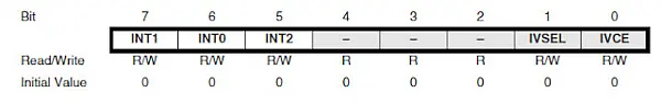
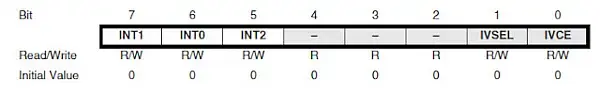
1- GICR (General Interrupt Control Register)
To trigger the external hardware interrupt, you need to initially activate the specific interrupt(s). This activation is achieved by configuring the corresponding INTx bit (where x = 0, 1, 2) in the General Interrupt Control Register (GICR), which is depicted below.
2- SREG (Status Register)
To enable the external interrupt, it’s necessary to set the I-bit in the Status Register (SREG) as well.
3- MCUCR (MCU Control Register)
By default, INT0, INT1, and INT2 operate as low-level triggered interrupts. This means that an interrupt is generated by the hardware when the signal at the interrupt pins is in a low state. However, it’s possible to configure INT0 and INT1 external interrupts to trigger based on a rising edge, falling edge, or any logical change in the input signal. On the other hand, INT2 is exclusively triggered by edge-level changes (either rising or falling).
To specify the type of signal state or transition at the interrupt input pins that will generate an interrupt for INT0 and INT1, the MCU Control Register (MCUCR) is used. The MCUCR configuration is provided below.
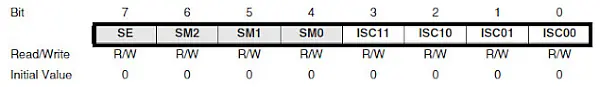
The ISC01 and ISC00 bits determine the interrupt sensitivity for external interrupt 0 (INT0). Their specific combination dictates the type of signal change that will activate the interrupt.
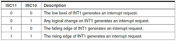
Likewise, the ISC11 and ISC10 bits determine the specific signal transition that triggers external interrupt 1 (INT1).
4- MCUCSR (MCU Control and Status Register)
Regarding INT2, the MCUCSR register’s ISC2 bit dictates whether rising or falling edge detection is employed to initiate an external interrupt.
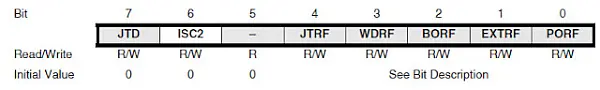
When the ISC2 bit is set to 0, the interrupt is triggered by the falling edge of INT2. Conversely, when it’s set to 1, the interrupt is generated by the rising edge of INT2.
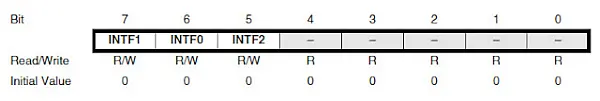
5- GIFR (General Interrupt Flag Register)
The GIFR register holds the flag bits INTF0, INTF1, and INTF2, which are raised when an external interrupt occurs. Monitoring these bits allows us to determine if an interrupt has taken place.
Programming ATmega32 External Interrupt
Example 1:
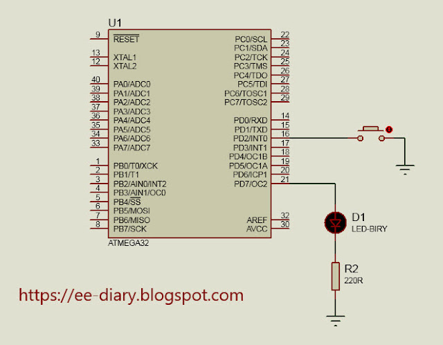
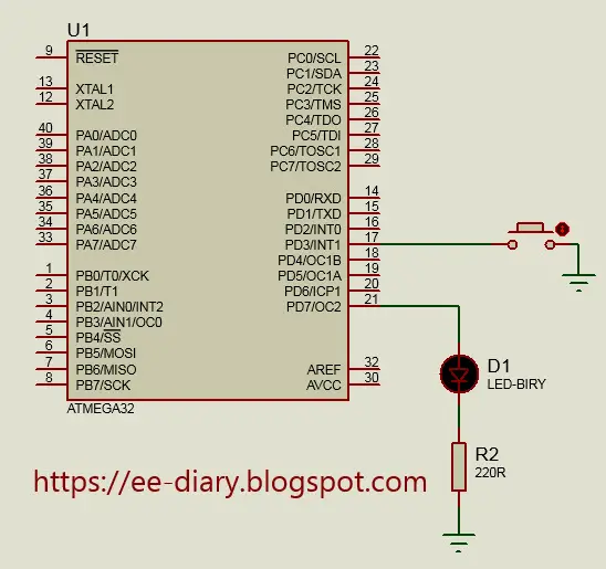
In the provided example code, we’ll utilize an external interrupt on INT0 (located on Port D pin 2). A switch is connected to the INT0 pin, with an internal pull-up, causing INT0 to read high under normal conditions. When the INT0 input goes low (by pressing the switch to ground), an interrupt is triggered. This interrupt toggles the state of an LED connected to Port D pin 7.
Below is the circuit diagram illustrating the external interrupt setup on the INT0 pin.
Program Code:
Below is the code for generating an external interrupt on INT0 and toggling the LED within the ISR (Interrupt Service Routine) for INT0.
#include <avr/io.h>

#include <avr/interrupt.h>


int main()

 {

DDRD |= (1<<PD7);//set PD7 as output for LED

PORTD |= (1<<PD2); //enable pull-up

GICR |= (1<<INT0);//enable external interrupt 0

sei();//enable global interrupt


   while (1);


return 0;

 }


ISR(INT0_vect){

PORTD ^= (1<<PD7);

}
Example 2:
In this example featuring an external interrupt, we’ll demonstrate the application of edge detection. We’ll utilize the INT1 external interrupt set to respond to a falling edge trigger. In this scenario, when INT1 transitions to a low state, it will toggle the LED connected to Port D pin 7 once.
The circuit diagram is presented below.
Program Code:
Below is the code to set up the INT1 external interrupt with a falling edge trigger.
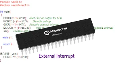
#include <avr/io.h>

#include <avr/interrupt.h>


int main()

 {

DDRD |= (1<<PD7);//set PD7 as output for LED

PORTD |= (1<<PD3); //enable pull-up

GICR |= (1<<INT1);//enable external interrupt 1

MCUCR |= (1<<ISC10);//set ISC10 bit to configure INT1 as falling edge triggered interrupt

sei();//enable global interrupt


   while (1);


return 0;

 }


ISR(INT1_vect){

PORTD ^= (1<<PD7);

}
- What pins provide external interrupts on the ATmega32?
INT0 on PD2, INT1 on PD3, and INT2 on PB2. - How do you enable a specific external interrupt?
Set the corresponding INTx bit in the GICR register. - How do you enable global interrupts?
Set the I-bit in the Status Register (SREG) using sei() in code. - How are INT0 and INT1 trigger types configured?
Use ISC01 and ISC00 for INT0 and ISC11 and ISC10 for INT1 in the MCUCR register. - Can INT2 be configured for level-triggered interrupts?
No, INT2 is configured for edge detection only via the ISC2 bit in MCUCSR. - How can you detect that an external interrupt occurred?
The GIFR register flags INTF0, INTF1, and INTF2 are set when their respective interrupts occur. - What does the example using INT0 demonstrate?
A switch with internal pull-up on INT0 (PD2) triggers an ISR that toggles an LED on PD7 when pressed. - What does the INT1 example demonstrate?
Configuring INT1 for falling-edge detection toggles the LED on PD7 when INT1 (PD3) goes low.