
Summary of Programming AVR ADC module with WinAVR using Atmega8 microcontroller
Most AVR microcontrollers include an on-chip ADC simplifying hardware and software design. Using the Atmega8 as an example, the ADC offers up to eight inputs (mostly 10-bit), selectable references (AREF, AVCC, internal 2.56V), separate AVCC/AGND pins, ±2 LSB accuracy, ±0.5 LSB INL, and up to 15 kSPS. It supports single and free-running modes and an ADC noise reduction sleep mode. The article shows initializing ADC (ADMUX/ADCSRA), starting conversions with channel multiplexing, enabling interrupts, and reading results (displaying on LCD).
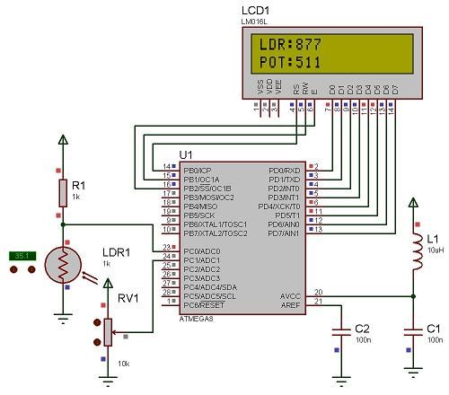
Parts used in theAtmega8 ADC example:
- Atmega8 microcontroller
- Photoresistor (LDR) connected to ADC0
- Potentiometer connected to ADC2
- LCD display for output
- Proteus simulator (optional for simulation)
- AVCC and AGND power supply connections
- AREF with external capacitor
Most of AVR microcontrollers have Analog to Digital Converter (ADC) integrated in to chip. Such solution makes embedded designers life much easier when creating projects and programming them. With no need external ADC PCB takes less space, easier to create programs – it saves time and money. As an example lets take Atmega8 microcontroller which have up to 8 ADC inputs most with 10-bit resolution(excluding ADC4 and ADC5 inputs that are 8-bit). All features of AVR internal ADC can be found on official ATMEL AVR datasheets, but most important to mention are:
-
±2 LSB accuracy – so measurements aren’t very accurate. If AREF voltage is 5V then error may reach ±0.04V but this is still good results for most of tasks;
-
Integral nonlinearity ±0.5 LSB;
-
Conversion speed up to 15kSPS at maximum resolution. This is far not enough for 20kHz audio signal sampling.
ADC unit is powered with separate power supply pins AVCC with AGND, but AVCC must not differ ±0.3V of VCC. Also ADC unit can have different voltage reference sources selectable in ADMUX register. References may be taken from AREF pin, AVCC with external capacitor or internal 2.56V voltage reference. All ADC inputs are multiplexed via multiplexer. Each channels can be selected by changing 4 bits in ADMUX register. ADC unit can operata in two modes:
-
Single conversion – when ADC converter makes one conversion and then stops. As this mode require ADC initialization for each conversion it takes 25ADC clock cycles;
-
Free running conversion – conversion is continuous. Once initialized it takes 13 ADC cycles for single conversion. In this mode ADC data register has to be read before new value is written.
AVR ADC has a nice feature ADC noise reduction technique which allows to perform conversion with minimal noise induced from AVR core and io peripherals. It is simple – when noise canceling is enabled MCU is put to sleep(CPU clock stops). After conversion completes interrupt wakes processor to read and process converted data.
All theory is nicely explained in AVR datasheets better lets go to some practical issues. Connect photo resistor to ADC0 input and simple potentiometer to ADC2. As an example lets do single conversions with AVCC voltage as reference. Lets generate an interrupt when conversion is complete. Interrupt service routine will output ADC value on LCD. Circuit is really simple – on Proteus simulator it is even simpler:
There are three simple steps needed to achieve desired results. First of all we need to initialize ADC. For this adc_init() function is written which prepares reference voltage source (AVCC with external capacitor at AREF pin), then enables ADC peripheral and performs single dummy conversion to initialize ADC.
void adc_init(void)
{
//select reference voltage
//AVCC with external capacitor at AREF pin
ADMUX|=(0<<REFS1)|(1<<REFS0);
//set prescaller and enable ADC
ADCSRA|=(1<<ADEN)|(1<<ADIE);//enable ADC with dummy conversion
//set sleep mode for ADC noise reduction conversion
set_sleep_mode(SLEEP_MODE_ADC);
}
Next step is to convert data itself. As we need to read values from two channels, there also multiplexing is needed.
void adc_start_conversion(uint8_t channel)
{
//remember current ADC channel;
ch=channel;
//select ADC channel
ADMUX=(ADMUX&0xF0)|channel;
//Start conversion with Interrupt after conversion
//enable global interrupts
sei();
ADCSRA |= (1<<ADSC)|(1<<ADIE);
}
If this conversion mode invokes an interrupt after conversion is complete, thidr step is writing interrupt service routine, which takes 10 ADC value and displays it on LCD:
For more detail: Programming AVR ADC module with WinAVR using Atmega8 microcontroller
- What ADC resolution does Atmega8 provide?
Most ADC inputs provide 10-bit resolution; ADC4 and ADC5 are 8-bit. - How accurate is the AVR ADC?
Typical accuracy is ±2 LSB, which at 5V AREF may be up to ±0.04V; integral nonlinearity is ±0.5 LSB. - Can the ADC sample audio signals at 20 kHz?
No; maximum conversion speed is up to 15 kSPS at maximum resolution, which is insufficient for 20 kHz audio sampling. - What reference sources can be used for the ADC?
References selectable in ADMUX are AREF pin, AVCC with external capacitor, or internal 2.56V reference. - How do you select ADC input channels?
ADC channels are selected by setting the four channel bits in the ADMUX register. - What modes does the ADC support?
It supports single conversion mode (25 ADC clock cycles per conversion) and free running mode (13 ADC cycles per conversion). - How does ADC noise reduction work?
Noise reduction puts the MCU to sleep (stopping CPU clock) during conversion and wakes it with an interrupt when conversion completes. - How is the ADC initialized in the example?
ADC is initialized by selecting AVCC as reference in ADMUX, enabling ADC and ADC interrupt in ADCSRA, performing a dummy conversion, and setting sleep mode to SLEEP_MODE_ADC. - How does the example start a conversion on a given channel?
It stores the channel, sets ADMUX lower bits to the channel, enables global interrupts (sei), and sets ADSC and ADIE bits in ADCSRA to start conversion with interrupt. - Where are conversion results displayed in the example?
The interrupt service routine reads the ADC value and displays it on an LCD.
