This project was done in order to experiment with the Automotakit breadboard board which is based on the ATMEGA256A3U chip. The use of a DAC, ADC , low pass filter, PWM, basic I/O, current control, clock setup, and interrupts on an Atmega chip are some of the topics explored here.
In order to experiment around, the datasheet and manual were used extensively along with a scope to mess around with values. Many lessons were learned through this project most heavily including the use of registers.
PID Test
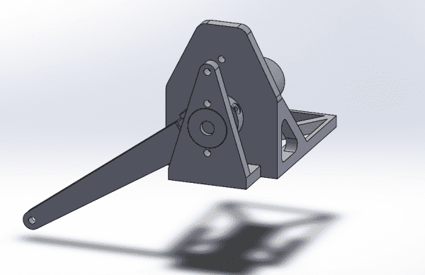
To incorporate all of the individual components, I wrote a project in which all the components are included to make a PID controller which drives a 3D-printed “clock”.
Lessons
-
-
- DAC
DAC()<< example in this code is meant only to use DACB due to poor construction
-
-
- Used to convert digital signals to analog signals – really useful for debugging on scopes
-
- DAC CTRLA – enable a channel on the DAC, and enable DAC
-
- CTRLB – set DAC to single channel use or dual channel use
-
- CTRLC – Set the reference voltage
-
- DAC Channel
-
- DACB.STATUS – used to check if its ready to convert again.
-
- DACx.CHyDATA – 12 bit value to output
-
-
-
- ADC
ADC(A
-
- DC, ADC_CH, ADC_CH_MUXPOS);
-
-
- Pass in the ADC you want to use. channel, and the Pin you want to sue for POS side(NEG is gnd here) Used to convert Analog signals to digital signals for processing. (i.e. – current sensing) ADC can be setup in multiple ways- first divide being between single or differential mode In the example, it is setup in differential mode W gain. CTRLA enable ADC
-
- CTRLB ADC Resolution
-
- REFCTRL Ref voltage
-
- PRESCALER ADC clock prescaler – ADC runs on its own clock- you want to make sure to run it down, otherwise you run into many problems.
-
- ADC Channel
-
- CTRL- channel input mode(DIFFWGAIN in this case) and the gain value, and to start a scan(1<<7) remember to check if scan is done being computed before doing again. Value 1<<7 is turned off when scan is done
-
- MUXCTRL – setting the positive and negative pins.
-
-
- Timer & PWM
PWM(Timer, Prescalar, pwm channel, base frequency, desired frequency)
-
-
- For PWM, you have to setup multiple things. You are using the Timer on the chip, so you have to setup its period(compare capture value with MAX 65536), its prescalar, its mode, along with the channel at which to output when the timer hits the compare value. Necessary Registers to run minimal PWM
-
- Timer
-
- CTRLA – prescalar – use the minimum amount in order to preserve as much resolution as possible
-
- CTRLB – Timer mode (Singleslope for PWM-> TC_WGMODE_SINGLESLOPE_gc) and the pwm channel on which to output given as TCX_CCXEN_bm type
-
- PERBUFL & PERBUFH – Hi and lo period values for timer. Timer counts up to this value and then restarts back to 0.
-
- Timer Channel
-
- CCXBUFH & CCXBUFL – compare value. When the Timer hits this value on its count up, it will change the output to low.
-
- Timer Interrupts
-
- Also uses Timer (should be obvious given by name 😉 )
-
- To set up, make sure that interrupts are enabled by including avr/interrupt.h, and calling sei(); and setting the PMIC CTRL pins to each level wanted (high, medium, and/or low level interrupts)
-
- Remember to set the pin you want as an output using PORTX.DIRSET register
-
- Timer
-
- CTRLA – setup prescalar
-
- PERBUFL & PERBUFH – setup period same as PWM above
-
- INTCTRLA – initiate the interrupt
-
- then, add a method without return type(not even void) named ISR(TCCX_OVF_vect), where X is your timer number with the contents that you want to loop over.
-
-
- PID
PID(P,I,D, dt, CONT, MIN & MAX IN & OUT, K)
-
-
- Typical PID sequence, with some added features. enable CONT in order to have a loop for a system that is circular (i.e. a 360 degree arm yes vs a 1d elevator no) Setup mininum and maximum outputs, with integral portion not allowed to go over the MAX& MIN Outs. Since the derivative portion can be quite noisy run at a very fast frequency, a low pass filter is automatically applied to the D value, with K being a constant used to change the low pass filter’s response time. See low pass filter for details on that. dt is the period of each loop.(1second /frequency)
-
- crunch(input) logic current error = setpoint – current value<<<<<< this is changed if it is CONT. If CONT, find the shortest distance to setpoint is the current error.
-
- total error+= current error;
-
- derivate error = filter(current error – previous error)
-
- output = P* current error + I* total Error + D* derivative error
-
- onTarget() logic
-
- if on target according to acceptable range for more than a certain amount of time, return true
-
- setAcceptableRange() logic
-
- set the acceptable range +- where range is sepoint+-acceptable range
-
- set Setpoint()
-
- Current Control(P, I, dt, MAX&MIN IN&OUT)
-
- Basic PI loop. I is used much more than normal, P being used for the initial ramp up. Same setup as PID loop, but without the derivative term
-
- crunch(input) logic
-
- current error = setpoint – current value
-
- the shortest distance to setpoint is the current error.
-
- total error+= current error;
-
- output = P* current error + I* total Error
-
- onTarget() logic
-
- if on target according to acceptable range for more than a certain amount of time, return true
-
- setAcceptableRange() logic
-
- set the acceptable range +- where range is sepoint+-acceptable range
-
- set Setpoint()
-
- Encoder w/ interrupts/ATKEncoder
-
- Encoders that automatically update based on interrupts running on a certain port.
-
- PORTX_DIRSET &= ~(PINx_bm | PINy_bm) – set the direction of the two input pins
-
- PORTX.INTCTRL – set the level of the interrupt(high/med/low)
-
- PORTX.INTzMASK= set the interrupt of the port towards a certain pin
-
- PORTX.PINxCTRL = set Pin to trigger on rising or falling edge
- (make sure one interrupt is set on falling and other on rising edge)
Source: Programming for AVR