For our ECE 4760 final project, we choose to develop an electronic push-up trainer that could monitor people’s movement, provide training package to optimize their push-up exercise and body health. A distance meter will be used to figure out whether the posture of the person is correct or not, and the touch screen used will be either an input and output device. It will take command and push-up input from user and display corresponding information. All I/O messages are processed by the Atmel micro-controller. There will be three modes of operation. They are easy mode (for beginners, have less number of sets and less push-ups each set), hard mode (for intermediate/veterans, have heavy number of sets and more push-ups each set), and record beating mode (for fun, will keep the maximum number of push-ups made in eeprom). This design will be totally safe for human with its low voltage electronics and interface fits all people group. Moreover, this project is not an available product in market. Thus, it will not violate any intellectual property. The goal for this project is to learn to how to use complex color LCD, resistive touch overlay and ADC.
High-Level Design
Rational and Inspiration
Health is important to human and push-up is an efficient way to exercise body and build body shapes. However, due to busy life-style and lack knowledge about physical exercise, a lot of people ignore daily exercises including push-up and their body movements are not proper. We come up with this idea because we find out that busy periods, such as before exams, we tend to ignore daily physical training and the body condition will simply keep getting worse and worse after exams. We thought that if there will be some “fun” device that can supervise people to do some daily work out, people would enjoy physical trainings. We choose push-up as one target training because it requires little space and is easy and efficient.
The motivation for this project was that such an electronic trainer would not only be helpful for one kind of training. In fact, it can be extended to more functionality such as a sit-up trainer etc. The combination of a MCU, touch screen and sensor system can satisfy needs for many kinds of in home physical training. The hope for this project is to implement the push-up ability. We have also note that there are past ECE 4760 project groups that have used touch-screen LCDs that can be used as reference. We will reference some hardware and software design to make the push-up trainer design more feasible, elegant, and easy to expand functionalities for further extensions.
High-Level Block Diagram
The high-level design will include four parts. They are user input, microcontroller unit (MCU), LCD display and sensor. User inputs will be taken by the touch screen LCD and the sensor system. And the touch screen and the sensor system will interact with the MCU.
1. Microcontroller: The microcontroller used for this project is Atmel Atmega 1284p, which is used in the ECE 4760 course. This controller has 32 general purpose input and output pins, where PORTB and PORTD pin sets will be used to handle the touch screen LCD. The PORTA set will be used as ADC to take sensor information and some of them will also be used for power switch and debugging purpose. In addition, the ECE 4760 course Atmega development board provides build-in USB interface for debugging that uses PORTD. Thus, PORTD 0 and 1 will be left untouched.
2. Touch Screen LCD: The Touch Screen LCD used in this project is suggested by Bruce Land. The ILI 9325 touch screen breakout board from Adafruit is used. Partial hardware and software setup will be referenced to previous project (Virtuoso: A Touchscreen Music App) for LCD display purpose. The touch part is implemented by using a resistive touch overlay. Thus, different voltage information will be fed into the microcontroller when various places are touched. Further breakout for the touch screen LCD will be shown in hardware design.
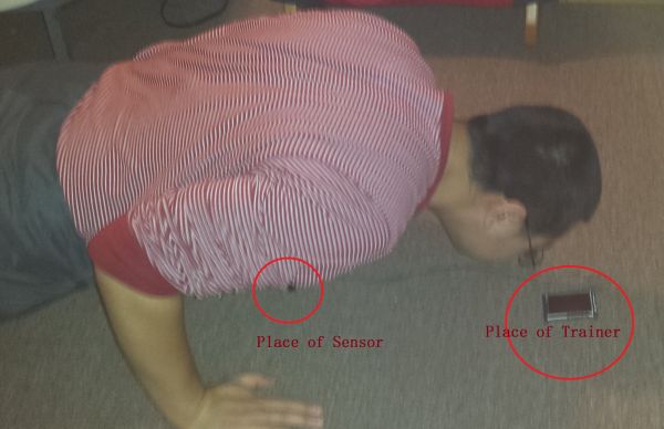
3. Sensors: We will use analog distance meter to measure whether the back of body is low enough when doing push-up, so that more muscle of body can be exercised and the purpose of this trainer is to monitor whether people’s physical movement is correct or not. The sensor will use infrared ray and take the reflection time of object to provide distance information.
4. User Input: User will use the touch screen by hand touching to select the desired training mode. (easy/hard/record) And when doing push-ups, user will need to use to nose to touch the designated circle region displayed by the LCD and keep back at a desired low position to achieve a successful push-up. Moreover, the user will also be able to choose other command prompted by the LCD by touching it.
Relevant Standards
Since IR distance sensing tools are used, it should follow exactly IEC/EN 60825-1 optical radiation standard to ensure safety for users, which should be implemented by the manufacture and the design group is responsible to verify it.
Hardware Design
Overview
From the high level diagram, it can be seen that connections must be built between the MCU circuit, touch screen LCD circuit and the sensor. Sections below will explain them in details. All connections are verified by both user manual provided by manufacture website and experiment.
The figure above shows the pin-out of the ILI 9325 touch screen breakout board from Adafruit. This LCD is a 2.8 inches TFT LCD screen that is connected to ILI 9325 controller chip, which is a 18 bit 262k, 240×320 resolution, and 172800 RAM one-chip SoC driver for a-TFT LCD driver. However, only half of the colour complexity is used in this breakout version that will make the programming and connection for LCD easier (D17-D0 are available, but only D7-D0 are used in this project). The D0-D7 pins are connected to the PORTA0-7 of the MCU. These pins are the LCD data pins that will take input data from microcontroller and send it to the ILI 9325 colour LCD controller so that proper image can be shown on the LCD. On the other hand, RST, RD, WR, C/D and CS pins are connected to PORTD’s of the microcontroller for LCD input control purpose so that the ILI 9325 knows when to take the input and what the desired input is. Backlite pin of LCD is connected to 5V from the MCU to light up the LCD screen. The Y-/+ and X-/+ are the analog output of the resistive touch overlay on top on the LCD screen. Both X- and Y- are always connected to ground because they are used for negative input only. When Y+ is connected to 5VDC, a varying voltage indicating the x-position can be read from the X+ pin. Similarly, y-position can be determined when X+ is applied with 5VDC. To achieve this, two TIP 125 PNP Darlington transistors are used as switches to open and close the connection between X/Y+ to 5V. The Collector is connected to 5VDC, base is connected to a digital output port (PORTA 6/7 used), and the emitter is connected to either X+ or Y+. This connection ensures that when base is high (5VDC), the collector and emitter channel is shut down. And when base is low, the channel is open and 5VDC is fed to either X+ or Y+. At the meantime, we read the pin that is not being supplied with 5VDC through ADC pins of microcontroller. Analog circuit diagram of the transistor is shown below. In the end, the 3-5V and GND is connected to the power and ground for power supply purpose.
Sharp Distance Meter
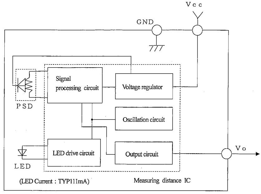
Model GP2Y0A41S0F Sharp analog output distance measuring sensor is used in this project to take measurement of body movement. It is capable of measuring distance from 4 to 30 cm, with an operation voltage of 5VDC and current of 12mA.
This sensor takes 4.5 to 5.5 VDC input and outputs the analog distance information in voltage from the Vo pin. It has a 5.0 ms maximum time delay from measurement to output that should be considered when running the while(1) loop in main. The connection is relatively simple that the VCC/GND corresponds to 5V and ground of the MCU circuit and the Vo is connected to PORTA2, which is an pre-defined to take analog input. In addition, since sensors are active elements, capacitors to low pass the power are applied. Thus, additional noises can be eliminated. Without these low pass capacitors (10uF), the microcontroller will randomly resets due to expected ground noise on the MCU circuit.
Moreover, another important factor lead to the choice of this sensor is the low current rating. This sensor requires only 12mA to operate, which is less than the nominal current (about 20mA) of the Atmel Atmega 1284p microcontroller. Previously, we have used another Sharp distance sensor that could measure long distance but with 70mA current rating. And that sensor will cause the microcontroller to reset periodically. To eliminate those hazards, we focused on low current requirement sensors and we finally determined to use the GP2Y0A41S0F Sharp analog output distance measuring sensor.
Microcontroller
In our final design project, we used the ECE 4760 development board with Atmega 1284p microcontroller. The circuit board provides USB interface that will allow easy on chip debug. On the other hand PORTA/B/C/D are all connected to required pins listed in previous sections and all connections will simply use bread board and wires available in lab. The picture below represents the all the elements that are used in this project. Detailed schematics are shown in the appendix.
Software Design
The programs for the microcontrollers are implemented in C. The compiler is WINAVR GCC C compiler and uses WinAvr 20100110 libraries, which contains necessary for general purpose input and output (GPIO) and also essential interrupt service routine (ISR). The editing environment is AVR Studio version 4.19, which is suggested by the course. The software design in this project will primarily involves three parts. ADC configuration, video library for the LCD and state machine design to switch between different modes.
ADC Code Design
The ADC related functions are implemented in touch.h. The get_touch() will take run the ADC for touch screen and the get_distance() will work for the distance meter. To begin with, the ADC will be initialized with ADMUX=(1<<ADLAR)|(1<<REFS0)|(1<<REFS1); ADCSRA=0x07; ADCSRA|=(1<<ADEN)|(1<<ADSC);. The internal 2.56V is set as voltage reference by the REFS0 and REFS1. We choose the 2.56V as reference after testing the maximum voltage output from either the touch screen or the distance meter and then find 2.56V is a feasible voltage reference value. The ADLAR=1 will make the high bits of ADC is representative. The most useful ADC values are stored in the 8 bit ADCH register. In addition, ADCH must be read before ADCL, which is the low bit registers. If read happens in the reverse order, the ADC system will be locked and no long works until reset or power off. The ADCSRA=0x07 is a divider that makes the ADC’s running clock matches with requirement about 125kHz. ADEN will simply enable the ADC and the ADSC will tell the ADC whether to start the conversion or not.
After the ADC initialization, we need to select different MUX number of ADMUX. For the get_touch() function, we first choose the ADMUX=(1<<ADLAR)|(1<<REFS0)|(1<<REFS1)| (1<<MUX0); so that PORTA1 is selected to be the ADC input. Then the ADCSRA|=(1<<ADSC); while(ADCSRA&(1<<ADSC)); will start the ADC and let it finish. After finishing, we can assign AY=ADCH so that we can start the x direction read. We did PORTA=0x80, output will trigger the BJT (connected as switch) to make Y+ pin 5VDC. Then we go through similar steps, we set MUX0=0, so that PORTA1 is selected to be the ADC input. When set the ADSC bit and wait for it to finish then record AX=ADCH. Then both X and Y direction information are all collected.
Furthermore, the get_distance() function also go through the same code sequence to obtain the voltage information from the sharp distance meter output pin. We connect the output to PORTA2, so we need to set the MUX1 of ADMUX equal to 1 when we perform the get_distance(). For debugging purpose, we have also added fprintf to each function so that we could observe the digital values after conversion. The figure below is a sample of the ADC putty screenshot.
Parts List:
| Part | Part Number | Source | unit Price | Quantity | Total Price |
| Touch Screen LCD | ILI9325 | Adafruit | 40 | 1 | 40 |
| Sharp Distance Meter | GP2Y0A41SK0F | Digikey | 7.4 | 1 | 7.4 |
| BJTs | TIP125 | Lab | 0 | 2 | 0 |
| Capacitors | 10uF | Lab | 5 | 0 | 0 |
| Wires | 16AWG | Lab | 0 | 20 | 0 |
| Bread Board | Lab | 0 | 1 | 0 | |
| Atmel Development Board | ECE 4760 | Lab | 5 | 1 | 5 |
| Atmel Microcontroller | Atmega 1284p | Lab | 5 | 1 | 5 |
| Total Price | 57.4 |
For more detail: Pushup Trainer Using Atmega1284