Summary of Rechargeable Battery Capacity Tester using Microcontroller ATMega168
This article describes a DIY rechargeable battery capacity tester built using an ATMega168 microcontroller. Unlike simple voltage testers, this device discharges AA NiCd and NiMH batteries while monitoring voltage to calculate total capacity in milliamp-hours (mAh). The system uses three independent discharge channels, an LCD for results, and alerts the user when testing is complete. It includes safety logic to prevent testing incompatible Li-Ion batteries by detecting initial voltage levels.
Parts used in the Rechargeable Battery Capacity Tester:
- Arduino board or ATMega168/328p chip
- Nokia 5510 graphic LCD
- Three MOSFETs
- Resistors for battery discharge
- Resistors for LCD interface
- Small PC speaker
- Circuit board or breadboard
- Modified AA battery holder
- Housing case
Do you have a pile of AA rechargeable batteries in your drawer? Some are old, some are new, but which sets would you bring with your camera on your next trip, and which ones are past their useful life? I like using rechargeable batteries, but I’m certain that some of them are not living up to the stated capacity on the label.
So how good are those batteries? Simple battery testers measure the voltage, but that’s not what we need – we want to find the overall capacity of the battery. How long will a battery last from the time it’s fully charged to the time that the “low battery” indicator comes on your device?
You can see this in action in a video in the last step of this instructable.
This is a job for a microcontroller

A simple way to test a battery would be to attach a load resistance to a fully charged battery and monitor the voltage until it drops below its useful value. The amount of time the battery lasts indicates its capacity.
That is a quick solution to the problem, but it involves watching a voltmeter for a few hours. That’s no fun at all. With a microcontroller, like the good old AVR chip, we can make a rechargeable battery tester that does the work for us. My tester puts AA batteries through a discharge test and reports the capacity in milliamp-hours (mAh) so you can compare battery capacity.
Design features
The tester can test multiple cells individually, and display the results on an LCD.
The tester discharges the battery while monitoring the voltage of the batteries. When the low threshold is reached, that cell is done it disconnects the load from the battery. When all tests are complete a series of beeps alerts the user. The tester identifies the type of battery by its initial voltage allowing both NiCd and NiMh batteries to be tested.
The design is based on the ATMega168 microcontroller, which has 6 A/D converters on the chip, so these will be used to read the battery voltages and determine the load current. Since each battery will require two A/D converters per cell, the maximum number of cells is three.
I built two of the testers, first using an Arduino board as a development system, and then a standalone device that will be more compact, and free up the Arduino for other projects.
Main Parts
Here’s what you need:
- An Arduino board
- or a ATMega168 or 328p chip and associated parts for the standalone version – see the schematic for details.
- A Nokia 5510 graphic LCD.
- Three MOSFETs — used to switch the resistive load on and off.
- Resistors to discharge the battery
- Resistors to interface to the LCD
- A small speaker typically found in PCs.
- Circuit Board or breadboard.
- A holder for AA batteries. This has to be modified so that each cell is wired individually.
- A case to house the projec
Circuit design
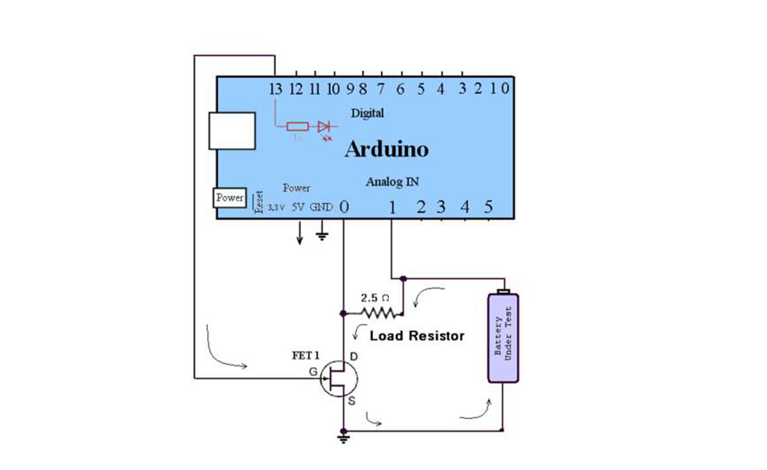
The discharging circuit is relatively simple, each battery has a corresponding load resistor that discharges the battery when the FET is switched ON. The switching is controlled by the microcontroller. The microcontroller’s A/D converter is used to monitor the battery’s voltage. A second A/D converter is connected to the FET to determine the current going through the load resistor. The current is calculated by subtracting the FET voltage from the battery’s voltage, which results in the voltage across the resistor. Dividing by the resistance gives the discharge current. Multiply this by the time and you get the milliamp-hour value.
If you look at the code, you’ll notice that the math is not quite this straightforward. The microcontroller reads the battery status every second, calculates the amount of charge drawn during the past second and adds it to the total. In that short amount of time there is only a fraction of a milliamp-hour that has been used, so it would be rounded off to zero if we’re not careful with our integer math. So instead of tallying the number of milliamp-hours, I tally the number of microamp-hours. That will be 1000 times larger so no worries of rounding down to zero. When milliamp-hours are displayed, the charge is divided by 1000.
The code is well commented, so the details can be seen there.
Load resistor
The resistor needs to dissipate a bit of power, so size does matter in this case. Testing NiCd and NiMH batteries (1.2 volts) the power dissipation is under 1 watt, so choose a sufficiently large resistor, or several resistors in parallel. With the relatively large current, be sure to use thick wire for the discharge path.
I considered allowing testing of type 14500 Li-Ion batteries since they are AA size too, but the load resistor would need to be changed to a larger value to accommodate the higher voltage. When the battery is inserted, the program checks the battery voltage, and does not perform the test if detects a Li-Ion battery. If I didn’t do this, the load resistor would draw over 1400 milliamps, which is way over the maximum recommended discharge current of 450 milliamps. The resistor would (in theory) dissipate about 6 watts, and the aroma of smoke would fill the room. This emphasizes the need for your code to test and handle unexpected conditions! I could have designed a circuit to allow testing of Li-Ion batteries by adding an additional FET and load resistor, but I didn’t need this feature.
Power MOSFET ( FET)
This component is like a switch. The output from the microcontroller controls the switch. When the output is high to the gate of the FET, it allows current to pass from the positive terminal of the battery, through the resistor, and the FET then completes the path back to the negative terminal. This discharges the battery over a period of time. I used a FET I salvaged from an old PC (partnumber IRL3103S). Any similar device should work as long as the Drain-to-Source On-Resistance is low. The 2M ohm resistor ensures the voltage read from an empty battery holder is zero volts. Without it, the A/D input will produce unpredictable results.
Display
I used a LCD from a old Nokia 5510 cell phone which was a pain to wire up, but the good news is that the display is available in an easy to use board from Sparkfun – along with the other materials. The Arduino is running at 5 volts, but the display and the control lines need no more than 3.3 volts. There are several ways to accomplish this – I chose using resistors to form a voltage divider. The 1800 ohm and 3300 ohm resistors form a pair that divide the 5 volt outputs from the Arduino to the desired 3.3 volts. In the standalone version I kept the design the same. I could have lowered the microcontroller’s voltage – the AVR chip will run at a lower voltage – but that would cause other design changes, so I kept the same design. The display has a back light, so I wired it up through a current limiting resistor. The Nokia display is a bit mapped display, so I took advantage of that and made animated battery icons to show the status of the three cells. The PCD8544 library makes controlling the display a snap http://code.google.com/p/pcd8544/
The above diagram is a simplified schematic showing one of the discharge circuits controlled by the Arduino.
For more Detail: Rechargeable Battery Capacity Tester using Microcontroller ATMega168
- How does the tester determine battery capacity?
The device discharges the battery while monitoring voltage over time to calculate the total charge drawn in milliamp-hours. - Can this tester identify different battery types?
Yes, it identifies NiCd and NiMh batteries by checking their initial voltage upon insertion. - Why does the code tally microamp-hours instead of milliamp-hours?
Tallying microamp-hours prevents integer math rounding errors during short one-second measurement intervals. - What happens if a Li-Ion battery is inserted?
The program detects the higher voltage and refuses to perform the test to avoid damaging the load resistor. - How is the current through the load resistor calculated?
The microcontroller subtracts the FET voltage from the battery voltage to find the resistor voltage, then divides by resistance. - What component is used to switch the resistive load on and off?
A Power MOSFET acts as a switch controlled by the microcontroller output. - How are the Arduino 5-volt signals converted for the display?
A voltage divider using 1800 ohm and 3300 ohm resistors reduces the 5-volt signal to 3.3 volts. - What alert mechanism notifies the user when tests are done?
A series of beeps from a small speaker alerts the user once all cells have finished testing.