Summary of Relay Timer with ATmega8 AVR MCU
This article describes a simple programmable timer using an ATmega8 microcontroller, a 16x2 LCD for UI, and a 3-button keypad to set countdown time. The timer displays remaining time during countdown and switches a load via a PCB-mount relay when the time elapses. Development used avr-gcc/AVR Studio, xBoard MINI, and eXtreme Burner for programming. Important notes: set high fuse C9 and low fuse FF, and adjust RV1 if display is blank.
Parts used in the Relay Timer with ATmega8 AVR MCU:
- ATmega8-16PU (U1)
- 16x2 LCD Module (LCD1)
- 16 MHz Crystal (X1)
- BC548 Transistor (Q1)
- 1N4007 Diode (D1)
- 4.7K Resistors (R1, R2)
- 10K Variable Resistor (VR1)
- 22pF Disk Capacitors (C1, C2)
- 0.1uF Disk Capacitors (C3, C4)
- Large Push Buttons (S1, S2, S3)
- PCB Mountable Relay (RL1)
Timer are widely used in industrial and domestic application for automating tasks. Microcontrollers can be used to design versatile and accurate timers with ease. Here I present a simple timer that can be used to turn on/off a load after user specified time.
The Timer uses a standard 16×2 lcd module for user interface (UI). User can set the time using a 3 button keypad.
After that Timer is started. While count down is in progress, the time left is displayed on screen.
The program use our LCD driver library more details of which can be found in here. Use avr-gcc + AVR Studio to compile.
The prototype was developed using xBoard MINI, a low cost easy to use ATmega8 development board. The program was burned to the MCU’s flash memory using eXtreme Burner – AVR Software and Hardware. A basic knowledge of working with different tools of AVR development is required, so please refer to following articles.
Note:
- Fuse Must be set as follows, HIGH FUSE=C9 LOW FUSE=FF (Very Important)
- If display is blank please adjust RV1
|
Part List
|
||
| 01 | ATmega8-16 PU | U1 |
| 02 | 16×2 LCD Module | LCD1 |
| 03 | 16 MHz Crystal | X1 |
| 04 | BC548 Transistor | Q1 |
| 05 | 1N4007 Diode | D1 |
| 06 | 4.7K Resistor | R1,R2 |
| 07 | 10K Variable Resistor | VR1 |
| 08 | 22pF Disk Capacitor | c1,c2 |
| 09 | 0.1uF Disk Capacitor | c3,c4 |
| 10 | Large Push Buttons | s1,s2,s3 |
| 11 | PCB Mountable Relay | RL1 |
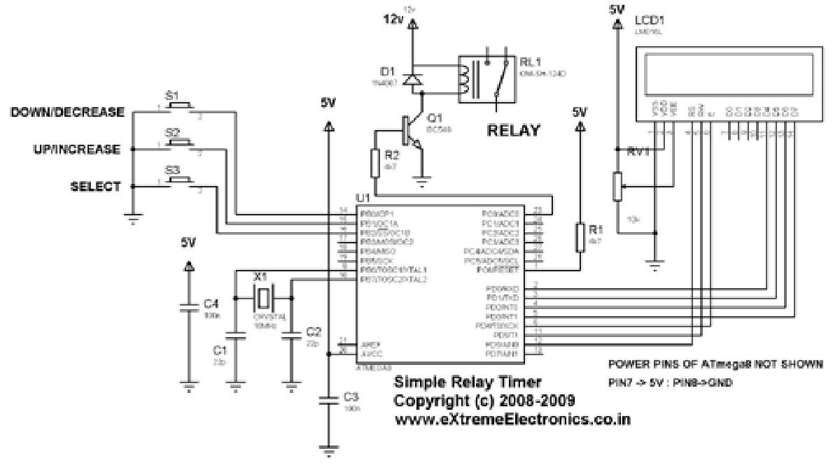
Schematic (Circuit Diagram)
Program
 /******************************************************
   A Simple Device Timer project designed using ATmega8
   AVR MVU. The Timer is usefully for keeping a device
   "ON" for a specific period of time. After the set
   time elapse the timer automatically turns the load off.
   The Timer uses a standard 16x2 lcd module for user interface
   UI. User can set the time using a 3 button keypad.
   After that Timer is started. While count down is in
   progress, the time left is displayed on screen.
   The program use our LCD driver library more details
   of which can be found in Web site.
   Use avr-gcc + AVR Studio to compile.
  ******************************************************/
#include <avr/io.h>
#include <avr/interrupt.h>
#include "lcd.h"
//Connection of Load
#define LOAD_DDR DDRC
#define LOAD_PORT PORTC
#define LOAD_POS PC0
//Global variable for the clock system
volatile unsigned int clock_millisecond=0;
volatile char clock_second=0;
volatile char clock_minute=0;
volatile char clock_hour=0;For more detail: Relay Timer with ATmega8 AVR MCU
- What microcontroller is used in this timer project?
The project uses the ATmega8 microcontroller. - How is the user interface implemented?
The user interface is a standard 16x2 LCD module. - How does the user set the time?
The user sets time using a 3-button keypad. - How is the load switched by the timer?
The load is controlled via a PCB-mountable relay driven from the microcontroller. - What tools are used to compile and program the MCU?
The code is compiled with avr-gcc + AVR Studio and flashed using eXtreme Burner - AVR Software and Hardware. - What fuse settings are required?
Set HIGH FUSE to C9 and LOW FUSE to FF. - What should I do if the LCD display is blank?
Adjust the RV1 variable resistor if the display is blank. - Which crystal frequency is used for the MCU?
A 16 MHz crystal is used.