
Summary of REMOTE CONTROLLED PROPELLER CLOCK CIRCUIT AT90S2313
This article describes a remote-controlled propeller clock circuit using the AT90S2313 microcontroller. It supports analog and digital display modes via Sony protocol control. The system drives 18 LEDs through a ULN2803 driver, powered by an MC34064 for low-voltage battery protection.
Parts used in the Remote Controlled Propeller Clock Circuit:
- AT90S2313 microcontroller (16MHz)
- Sony control protocol
- Analog clock view mode
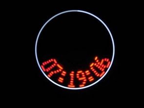
- Digital clock view mode
- 18 LEDs
- ULN2803 driver
- MC34064 integrated low-voltage detector
Before air time, “Propeller Clock” projects I shared in this project control and mode selection can be achieved in both analog clock and digital clock view modes control for the Sony control protocol used… Electronics Projects, Remote Controlled Propeller Clock Circuit AT90S2313 “avr project, microcontroller projects, “
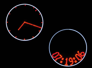
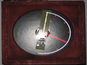
Before air time, “Propeller Clock” projects I shared in this project control and mode selection can be achieved in both analog clock and digital clock view modes control for the Sony control protocol used control floor Atmel AT90S2313 microcontroller available (16MHz) logout the LEDs (18 LEDs) to drive ULN2803 RES pin AT90S2313 has also been used in the MC34064 is used in the integrated low-voltage detection for use with battery guess how necessary a kind of protection do not know …

Source: REMOTE CONTROLLED PROPELLER CLOCK CIRCUIT AT90S2313 alternative link: remote-controlled-propeller-clock-circuit-at90s2313.rar
- How is control and mode selection achieved?
Control and mode selection are achieved using the Sony control protocol. - What display modes does the project support?
The project supports both analog clock and digital clock view modes. - Which microcontroller is used in this circuit?
The Atmel AT90S2313 microcontroller is used. - What is the operating frequency of the microcontroller?
The microcontroller operates at 16MHz. - How many LEDs are driven in this project?
The circuit drives 18 LEDs. - Which component is used to drive the LEDs?
A ULN2803 driver is used to drive the LEDs. - Why is the MC34064 used in the circuit?
The MC34064 is used as an integrated low-voltage detection component for battery protection. - Can the project work with batteries?
Yes, the MC34064 provides necessary protection for use with batteries.
