In these days we’re here with our subsequent assignment that is RFID and keypad primarily based security machine. This assignment is implemented by means of the use of 8051. often we are able to see RFID tags or card in metro teach when we’re going to someplace then we need to apply a RFID tag has some records and RFID readers, that may read and write statistics to RFID tags. RFID carries a RFID tag which has 12 digit serial wide variety that’s read by using FRID Reader.
Step 1: Sections of Project
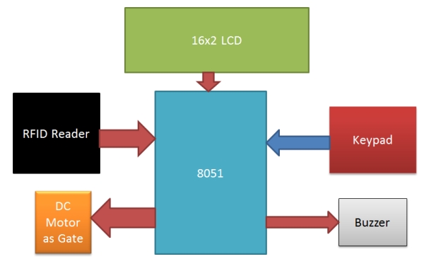
RFID Reader Section: This phase contains a RFID, which is an electronics tool which has part one is RFID Reader and other is RFID tag or Card. while we placed RFID tag to close to the RFID reader it reads tag information serially. RFID tag which we have used has 12 digit man or woman code or serial range. This RFID is running at baud fee of 9600 bps.
Keypad: 4×4 matrix keypad is used for entering the password for the system.
Control section: 8051 microcontroller is used for controlling entire the procedure of this project. here by way of using 8051 we are receiving RFID data and sending results or messages to liquid crystal display.
Display section: and 16×2 LCD is used in this project for displaying results and messages on it.
Driver section: this Section has a motor driver L293D for open and closed the gate and a buzzer with a BC547 NPN transistor for alert.
Step 2: Working
Operating of this project is easy. When someone put their RFID tag over RFID reader then RFID reads tag’s data and ship to 8051 microcontroller after it, microcontroller compares this received data with predefined data or records. If data is matched with predefined data or records then microcontroller ask for password and after coming password into microcontroller it starts to examine password with predefined password. If password in correct then gate will opened and in any other case liquid crystal display displayed access denied and buzzer begin beeping for a while.
Step 3: Circuit
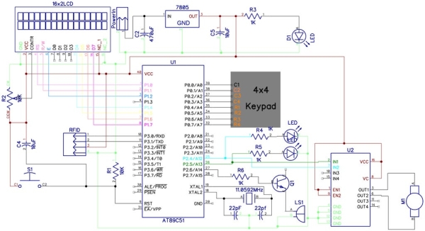
liquid crystal display is hooked up in 4 bit mode with microcontroller. lcd’s RS, RW and EN pins are connected at PORT 1 pin number P1.0, P1.1 and P1.2. D4, D5, D6 and D7 pins of lcd are linked at pin P1.4, P1.5, P1.6 and P1.7 of port 1. Motor is hooked up at PORT pin number P2.4 and P2.5. And buzzer is hooked up at P2.6 at PORT2. And keypad is hooked up at PORT0. Keypad row are connected at P0.4 – P0.7 and Columns are linked at P0.0 – P0.3.
Step 4: Program

Define pins for Input and output
like keypad, LCD, buzzer, LED motor etc.
Source: RFID Based Home Security System Using 8051