
Summary of RFID based security system using AVR ATmega32 microcontroller
This article details the design of a cost-effective RFID-based security system using an AVR microcontroller. It outlines how RFID tags with unique 12-bit IDs are read via UART communication, processed by an ATmega32, and used to control three relays for different access levels (Master, Student, Guest). The system includes logic to activate specific doors based on tag identification and automatically deactivate them after five seconds to prevent unauthorized tailgating.
Parts used in the RFID Based Security System:
- Microcontroller AVR Atmega32
- RFID reading module
- RFID TAGs
- LCD display module
- MAX232 circuit
- Interconnecting wires (Jumper wires)
- Relays
RFID technology has significantly revolutionized our lives by streamlining machine communication. Its widespread use spans across various sectors such as schools, hospitals, industries, and more. This article provides guidance on constructing a straightforward yet dependable RFID-based security system utilizing an AVR microcontroller, a solution that proves both reliable and cost-effective. Prior familiarity with RFID principles and interfacing is essential. Therefore, it’s recommended to review the “How to interface RFID with AVR Microcontroller” tutorial before embarking on this project.
DESIGN OF RFID BASED SECURITY SYSTEM:
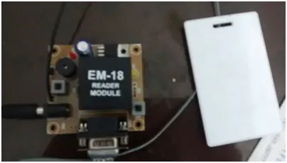
The setup involves an RFID reader module and RFID tags that utilize UART serial communication for interaction. When an RFID tag enters its range, the RFID module detects and captures the tag’s 12-bit ID. This unique identification code is then transmitted to the Microcontroller through the UART protocol for subsequent processing. Since the module functions within the RS232 logic range of +25V to -25V, an IC MAX232 level converter is necessary to convert the data to TTL logic, suitable for Microcontrollers.
To activate the doors, three relays should be linked to PORTB. For simplicity in the schematic design, only one relay was depicted above. If the RFID reader provides data in TTL logic, the use of MAX232 for conversion can be disregarded.
SCENARIO:
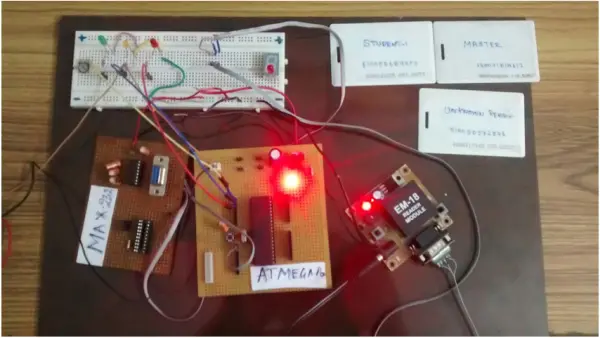
In this project, a school-level security scenario was selected to illustrate the system’s functionality. Each tag corresponds to a specific security level. For instance, a professor (identified by the “MASTER TAG”) possesses access to all school rooms and floors, while a student (identified by the “STUDENT TAG”) is granted access solely to classrooms. Guests, identified by the “GUEST TAG,” are restricted to accessing only the lobby area. Three relays from PORTB serve as door activators for these designated areas.
I possess three RFID tags: “MASTER,” “STUDENT,” and “GUEST.” When the RFID reader detects the “MASTER TAG,” all three relays are activated, allowing the professor unrestricted access to all rooms. In the case of the “STUDENT TAG,” only the relay connected to the classroom door is activated, granting access exclusively to that area. Lastly, when the RFID reader recognizes the “GUEST TAG,” only the relay controlling the lobby door activates, restricting access solely to the lobby area.
ALGORITHM:
1. Set up UART communication within the controller.
2. Begin scanning for tags using the RFID reader.
3. Sequentially read the 12-byte RFID ID via UART upon tag detection.
4. Compare the ID with stored records and retrieve the security level associated with the identified ID.
5. Trigger the relay or open the door based on the assessed security level.
6. Pause for five seconds and deactivate the relay to prevent unauthorized access (tailgating).
COMPONENTS USED:
1. Microcontroller AVR Atmega32
2. Module for RFID reading
3. RFID TAG
4. Module for LCD display
5. Circuit MAX232
6. Interconnecting wires (Jumper wires)
CODE:
- #include<avr/io.h>
- #include
- #include
- voidusartinit();
- //unsigned char a;
- unsignedcharvalue[15];
- unsignedint b;
- unsignedint k=0,i=0,j,l;
- unsignedchar value1[]={“140071D1A612”}; //Predefined ID
- unsignedchar value2[]={“51005D6899FD”};
- intmain ()
- {
- DDRC=0xFF;
- DDRB=0xFF;
- PORTB=0x00;
- usartinit();
- while(1)
- {
- while((UCSRA)&(1<<RXC))
- {
- value[i]=UDR;
- _delay_ms(1);
- i++;
- if(i==12)
- {
- value[i]=”;
- for(j=0;value1[j]!=”;j++)
- {
- if(value[j]==value1[j])
- k++;
- }
- if(k==12) //Match with the predefined ID
- {
- PORTB|=(1<<0)|(1<<1)|(1<<2); //Master have access to all rooms
- _delay_ms(5000);
- PORTB=0x00;
- }
- else
- {
- k=0;
- for(j=0;value2[j]!=”;j++)
- {
- if(value[j]==value2[j])
- k++;
- }
- if(k==12)
- {
- PORTB|=(1<<1); //Student have access to class rooms only
- _delay_ms(5000);
- PORTB=0x00;
- }
- else
- {
- PORTB|=(1<<2); //Guest have access to lobby only
- _delay_ms(5000);
- PORTB=0x00;
- } } } } } }
- voidusartinit()
- {
- UBRRH=00;
- UBRRL=77;
- UCSRB|=(1<<RXEN);
- UCSRC|=(1<<URSEL)|(1<<UCSZ0)|(1<<UCSZ1);
- }
-
What is the primary purpose of the MAX232 IC in this project?
The MAX232 level converter is necessary to convert data from the RS232 logic range (+25V to -25V) to TTL logic suitable for the Microcontroller. -
How does the system determine which door to open?
The system compares the scanned 12-byte RFID ID with stored records to retrieve the associated security level and triggers the corresponding relay. -
What happens when a MASTER TAG is detected?
When the reader detects the MASTER TAG, all three relays are activated, allowing the professor unrestricted access to all rooms. -
How long does the relay stay active after a valid tag is scanned?
The relay remains active for five seconds before deactivating to prevent unauthorized access or tailgating. -
Which communication protocol is used between the RFID reader and the microcontroller?
The setup utilizes UART serial communication for interaction between the RFID module and the Microcontroller. -
Can the MAX232 be omitted from the circuit?
Yes, if the RFID reader provides data in TTL logic, the use of MAX232 for conversion can be disregarded. -
What area does a GUEST TAG grant access to?
A GUEST TAG is restricted to accessing only the lobby area, activating only the relay controlling the lobby door.
