Summary of RGB Rotary Encoder with PWM and ISRs Using an ATmega328
This article details a project using an RGB rotary encoder with an Arduino or ATmega328 microcontroller. It explains configuring pin change interrupts for rotation, external interrupts for the button, and PWM for the RGB LED. The author also demonstrates functionality using three separate LEDs to visualize forward, backward, and push actions.
Parts used in the RGB Rotary Encoder Interface:
- RGB rotary encoder
- Three LEDs
- Resistors
- Arduino or ATmega328 microcontroller
- External pull-down resistor for the switch
Description
A long time ago I bought a couple RGB rotary encoders from Sparkfun because they were cheap and I was already spending a bunch on other stuff. I thought they would be neat for some interfaces since it includes a push button. The interrupt service routine (ISR) for pin changes on the rotary encoder (for terminals A and B, which will from this point be referred to as AB) can be found in this post (Oleg covers this topic in good detail, so I will not be recapping much on pin change interrupts). We will also need to add an external interrupt for the button. Lastly we will configure the PWM for the RGB LED that is contained withing the encoder. (I also have three separate LEDs set up to demonstrate the the actions from the rotary encoder: forward, backward, and push button).

Oleg, in one of his earlier posts, explains how to use a rotary encoder with a look up table. Basically the principle works by polling the current port and comparing to the previous reading. By comparing the previous states of AB to the current we can determine forward or reverse motion. For more detail see Oleg’s post.
Oleg, in one of his earlier posts, explains how to use a rotary encoder with a look up table. Basically the principle works by polling the current port and comparing to the previous reading. By comparing the previous states of AB to the current we can determine forward or reverse motion. For more detail see Oleg’s post.
Parts
You will need an RGB rotary encoder (or, as you can use three LEDs if you do not have an RGB rotary encoder), three LEDs/resistors to observe correct functionality, and an Arduino or an ATmega328 (or comparable) mcu.
Circuits
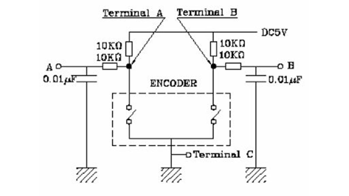
The following was taken from the datasheet for the RGB rotary encoder:
This is the suggested R/C filter from the datasheet to help avoid chatter (bounce). There is also a timing diagram in there that describes a time period that would mask chatter. Although the R/C filter should help alleviate chatter the chatter timing mask they mention is only 3ms, so a little chatter should not really effect anything (depending on what your ISR will do).
A and B will be connected to the first two pins on whatever port we choose to use (if the first two pins aren’t chosen you will have to change the way that you read the port and compare your last values). Terminal C goes to ground.
This next diagram comes from the dimensional drawing:
In this picture note that pin 5 is a common anode and pin three is for the switch/button.
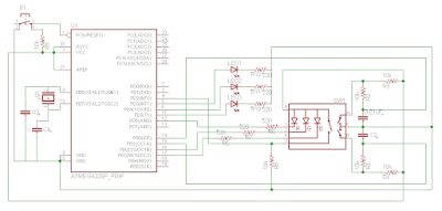
Left is from the dimensional drawing of the pins. Right is the actual dimensional drawing of the encoder. A resistor is needed between each LED and its corresponding output from the ATmega328. We also need a pull-down resistor on the switch. NOTE: The switch is very easily destroyed with heat. It will most likely break if you continue to heat it up and move it around when soldering. Figure out where you want it and leave it there.
The three LEDs that are not part of the encoder are for testing/demonstration. If you are using an Arduino ignore the crystal, caps, and switch on the left (Here is a diagram of the uno with pinouts describing how they relate to the ATmega328. It’s well done).
For more detail: RGB Rotary Encoder with PWM and ISRs Using an ATmega328
- How do I determine forward or reverse motion?
By polling the current port and comparing it to the previous reading of pins A and B. - Can I use separate LEDs instead of the RGB encoder?
Yes, you can use three LEDs with resistors if you do not have an RGB rotary encoder. - What is the purpose of the R/C filter mentioned?
The R/C filter helps avoid chatter or bounce on the signal lines. - Which pin is the common anode on the encoder?
Pin 5 is identified as the common anode. - Where should the switch terminal be connected?
Terminal C goes to ground, and the switch itself requires a pull-down resistor. - Does the datasheet specify a time period for masking chatter?
Yes, the timing diagram describes a time period that would mask chatter, noted as 3ms.