
Summary of SEPIC/Ćuk converter sprouts second output
This article presents a dual-output hybrid SEPIC-Ćuk converter designed to generate positive and negative supply voltages from a single input. The unregulated negative output mirrors the positive regulated output, which can be higher or lower than the input voltage. The analysis utilizes inductor volt-second balance and capacitor charge balance principles under continuous conduction mode to derive equations for output voltages based on duty cycle and load resistances.
Parts used in the Dual-Output Hybrid SEPIC-Ćuk Converter:
- MOSFET
- Diode
- Inductors (L1, L3)
- Capacitors (C2, C4, C5)
- Resistive Loads (RL1, RL2)
- Voltage Source (VIN)
Many applications require positive and negative supply voltages, with only one voltage requiring tight regulation. This Design Idea describes a dual-output, hybrid SEPIC–Ćuk converter whose positive output voltage can be lesser or greater than the input voltage. The unregulated negative output is a mirrored replica of the positive output.
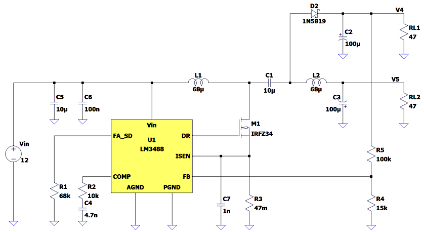
To find out the output voltages we apply the principle of inductor volt-second balance and capacitor charge balance. To simplify the calculus, we neglect the voltage drop over the MOSFET and diode and we consider only continuous conduction mode.
When the MOSFET is on we have this equivalent network:
Figure 2 Equivalent circuit in switch on-state
The inductor voltages and capacitor currents for this interval, using small-ripple approximation, are:
V1 = VIN
V3 = V2+V5
I3 = -I2
I4 = -V4/RL1
I5 = -I2-V5/RL2
When the MOSFET is off we have this equivalent network:
Figure 3 Equivalent circuit in switch off-state
and the inductor voltages and capacitor currents for this interval are:
V1 = VIN-V2-V4
V3 = V5-V4
I3 = I1
I4 = I1+I2-V4/RL1
I5 = -I2-V5/RL2
Equating the average inductor voltages and capacitor currents over one switching period to zero, we get:
v1_avg = D × VIN + (1-D) × (VIN-V2-V4) = 0
v3_avg = D × (V2+V5) + (1-D) × ( V5-V4) = 0
i3_avg = D × (-I2) + (1-D) × I1 = 0
i4_avg = D × (-V4/RL1) + (1-D) × ( I1+I2-V4/RL1) = 0
i5_avg = D × (-I2-V5/RL2) + (1-D) × ( -I2-V5/RL2) = 0
where D is the duty cycle.
Solving for V4 and V5:
V4 = Vin × RL1/(RL1+RL2) × D/(1-D)
V5 = -Vin × RL2/(RL1+RL2) × D/(1-D)
In practice, due to the feedback, the positive output voltage, V4, is fixed.
Extracting the duty cycle from the V4 equation and inserting it into V5 results in:
V5 = -RL2/RL1 × V4
Therefore, this topology is most suitable when the output currents do not differ much.
When the two loads are equal, then:
V4 = VIN/2 × D/(1-D) and
V5 = -VIN/2 × D/(1-D)
A variation of the topology can supply a “floating” load.
Read more: SEPIC/Ćuk converter sprouts second output
- What is the primary function of this design idea?
The design describes a dual-output, hybrid SEPIC-Ćuk converter that provides a regulated positive output and an unregulated negative mirrored output. - How are the output voltages calculated?
Output voltages are found by applying the principle of inductor volt-second balance and capacitor charge balance while neglecting MOSFET and diode voltage drops. - Does the positive output voltage have to be lower than the input voltage?
No, the positive output voltage can be lesser or greater than the input voltage. - Can this topology supply a floating load?
Yes, a variation of the topology described can supply a floating load. - When is this topology most suitable regarding load currents?
This topology is most suitable when the output currents do not differ much. - What happens to the output voltages when the two loads are equal?
When loads are equal, V4 becomes VIN divided by 2 multiplied by D over 1 minus D, and V5 is the negative version of that value. - How is the negative output voltage related to the positive output voltage?
The negative output voltage V5 equals the negative ratio of RL2 to RL1 multiplied by the positive output voltage V4. - What assumption is made about the switching mode during calculus?
The analysis considers only continuous conduction mode to simplify the calculus.
