Summary of Reverse engineering the 76477 sound effect chip
The article reverse-engineers the 1978 76477 Complex Sound Generation chip used in games like Space Invaders. It details how analog circuits, including a VCO, SLF oscillator, one-shot, envelope generator, and digital noise mixer, create diverse sound effects. The analysis explains the construction of NPN/PNP transistors and resistors on the silicon die, highlighting the prevalence of current mirrors and comparators in the design.
Parts used in the 76477 Chip:
- Voltage-controlled oscillator (VCO)
- Super low frequency (SLF) oscillator
- One-shot pulse generator
- Envelope generator
- Digital white noise generator
- Digital mixer
- Output amplifier
- NPN transistors
- PNP transistors
- Resistors
Remember the old video game Space Invaders? Some of its sound effects were provided by a chip called the 76477 Complex Sound Generation chip. While the sound effects1 produced by this 1978 chip seem primitive today, it was used in many video games, pinball games. But what’s inside this chip and how does it work internally? By reverse-engineering the chip from die photos, we can find out. (Photos courtesy of Sean Riddle.) In this article, I explain how the analog circuits of this chip works and show how the hundreds of transistors on the silicon die form the circuits of this complex chip.
The 76477 chip combines several functional blocks to produce a variety of sound effects. A voltage-controlled oscillator (VCO) produces a signal whose frequency depends on the control voltage. A “super low frequency” SLF oscillator generates a triangle wave. Feeding this into the VCO generates a varying pitch, useful for bird chirps, sirens, or the warbling sound of the UFO in Space Invaders. A “one-shot” produces a pulse of a fixed length to control the length of the sound. An envelope generator makes the sound more realistic by ramping its amplitude (volume) up at the start and down at the end. A digital white noise generator can be used for drums, gunshots, explosions and other similar sound effects. Finally a digital mixer combines these signals and feeds them to the output amplifier.
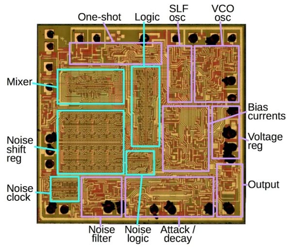
The diagram below indicates the functional blocks on the 76477 die. Looking under a microscope, you can see the circuitry that makes up the chip. The yellowish lines are metal traces that connect the circuits of the die. The reddish and greenish regions are the silicon of the chip, forming transistors and resistors. The black blobs around the edges of the chip show where tiny bond wires connected the die to the integrated circuit pins. Analog circuits are outlined in purple, while digital circuits are in cyan. The 76477 is primarily analog—most control signals are analog, the chip has no digital registers, and most sounds are generated from analog circuits—but about a third of the chip’s area is digital logic.2
The block diagram below shows the chip’s functional elements and can be compared to the die photo above. The chip is primarily controlled by resistors (red pins), capacitors (cyan pins) and voltages (violet pins). This made the chip difficult to control with a microprocessor, and more useful for hardwired sounds.
The remainder of this article will dive into the internals of the 76477 chip. First I’ll show how transistors and resistors are built on an integrated circuit. Next I’ll explain two key analog building blocks: the current mirror and the comparator. Finally, I’ll show the reverse-engineered circuits for the 76477’s analog functional modules and discuss how they operate. (I’ll describe the chip’s digital logic in a future article.)
Integrated circuit transistors and resistors
A bipolar integrated circuit such as the 76477 is built from two types of transistors: NPN and PNP. The diagram below shows two transistors on the 76477 die, with the emitter, base and collector labeled. The N-doped silicon appears reddish, while P-doped silicon appears green. Metal lines (yellowish) on top of the silicon connect the circuits, with outlines visible where metal is connected to the silicon layer. The transistor on the left is an NPN transistor. Internally, the transistor is built vertically, with the emitter on top, the base forming a thin layer beneath the emitter, and the collector region underneath. The transistor on the right is a PNP transistor. The collector forms a ring surrounding the central emitter. 3
Resistors are an important component of analog circuits. On a silicon chip, they can be formed from a long, narrow region of doped silicon with higher resistance. On an IC, resistors take a lot of space and are inaccurate, so they are generally avoided where possible. The die image below shows three resistors, which appear red in the photo. They are connected to the metal wiring at the contact points marked with blue arrows.
If a metal wire needs to cross another metal wire, the signal can use the silicon layer to pass under the wire. Two of these cross-unders are shown below. The silicon (green) is doped to be lower resistance than in the case of a resistor. Cross-unders are higher resistance than metal wiring, so they are only used when necessary.
By carefully examining the die photo, you can pick out the transistors and resistors and determine how they are connected. From this, you can reverse-engineer the chip’s circuits.
The current mirror
A key component of most analog circuits is the current mirror, and the 76477 is no exception, containing many current mirrors. A current mirror takes one reference current and “clones” it, generating a current that matches the reference current. Either of the symbols below can be used to indicate a current mirror or current source.
Read more: Reverse engineering the 76477 sound effect chip
- What is the primary function of the 76477 chip?
The chip combines functional blocks to produce a variety of sound effects for video games and pinball machines. - How does the SLF oscillator contribute to sound generation?
It generates a triangle wave that feeds into the VCO to create varying pitch sounds like bird chirps or UFO warbles. - What components are used to build the integrated circuit?
The chip is built from NPN and PNP bipolar transistors, resistors formed from doped silicon, and metal traces. - Why was the 76477 difficult to control with a microprocessor?
The chip is primarily controlled by resistors, capacitors, and voltages rather than digital registers. - What is the purpose of a current mirror in this chip?
A current mirror takes a reference current and clones it to generate a matching current for analog circuits. - Which part of the chip is responsible for drum and explosion sounds?
The digital white noise generator produces sounds like drums, gunshots, and explosions. - How are cross-unders implemented on the silicon die?
Signals use the doped silicon layer to pass under metal wires when two metal lines need to cross. - What percentage of the 76477 area consists of digital logic?
About one-third of the chip's area is dedicated to digital logic while the rest is analog.