
Summary of A simple brushless sensored motor driver for AVR Atmega
This article explains the operation of Brushless DC (BLDC) motors, detailing how integrated inverters drive synchronous motors using AC signals derived from a DC source. It covers rotor position detection via Hall effect sensors or back EMF, the six-state commutation sequence for three-phase coils, and the role of electronics in controlling speed and direction. The author describes a specific project implementing a simple sensored motor driver for an AVR Atmega microcontroller to manage these operations.
Parts used in the BLDC Motor Driver Project:
- Brushless DC motor (BLDC motor)
- AVR Atmega microcontroller
- Hall effect sensors
- Integrated inverter/switching power supply
- Three phase coils (U, V, W)
- Rotor with permanent magnets
Brushless electric motor (BLDC motors) are synchronous motors that are powered by a DC electric source via an integrated inverter/switching power supply, which produces an AC electric signal to drive the motor. Additional electronics control the inverter output amplitude and waveform (and therefore percent of DC bus usage/efficiency) and frequency (i.e. rotor speed). Because the controller must direct the rotor rotation, the controller requires some means of determining the rotor’s orientation/position (relative to the stator coils). Some designs use Hall effect sensors or a rotary encoder to directly measure the rotor’s position, others measure the back EMF in the undriven coils to infer the rotor position, eliminating the need for separate Hall effect sensors, and therefore are often called sensorless controllers.
The following explanation is taken from “AVR443: Sensor-based control of three phase Brushless DC motor” sheet.
Theory of operation: A three phase BLDC consists of a Stator with a number of coils. The fundamental three phase BLDC motor has three coils. Usually the three coils are referred to as U, V and W. In many motors the fundamental number of coils are replicated to have smaller rotation steps and smaller torque ripple. The rotor in a BLDC motor consists of an even number of permanent magnets. To simplify the explanation of how to operate a three-phase BLDC motor a fundamental BLDC with only three coils is considered. To make the motor rotate the coils are energized (or “activated”) in a predefined sequence, making the motor turn in one direction, say clockwise. Running the sequence in reverse order the motor run in the opposite direction. The direction of the current determines the orientation of the magnetic field generated by the coil. The magnetic field attracts and rejects the permanent magnets of the rotor. By changing the current flow in the coils and thereby the polarity of the magnetic fields at the right moment – and in the right sequence – the motor rotates. Alternation of the current flow through the coils to make the rotor turn is referred to as commutation. A three-phase BLDC motor has six states of commutation. When all six states in the commutation sequence have been performed the sequence is repeated to continue the rotation. The sequence represents a full electrical rotation. For motors with multiple poles the electrical rotation does not correspond to a mechanical rotation. A four-pole BLDC motor uses two electrical rotation cycles to per mechanical rotation. When specifying the number of Rotations Per Minute subsequently, the number of
electrical rotations is referred to unless otherwise mentioned. The most elementary commutation driving method used for BLDC motors is an on-off scheme: A coil is either conducting (in one or the other direction) or not conducting. The strength of the magnetic field determines the torque and speed of the motor. For BLDC motors the commutation control is handled by electronics. The simplest way to control the commutation is to commutate according the outputs from a set of position sensors inside the motor. Usually Hall sensors are used, but even back EMF can be used to detect the stator position. A common commutation is the one represented by the image below.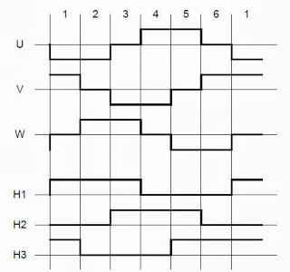
For this project, I’ve implemented a simple brushless sensored motor driver for AVR Atmega. The code i propose it’s not perfect, and can be improved, but for the needs i had it works.
For more detail: A simple brushless sensored motor driver for AVR Atmega
-
How does a BLDC motor receive power?
It is powered by a DC electric source via an integrated inverter that produces an AC electric signal. -
What determines the rotor orientation in a BLDC motor?
The controller requires means like Hall effect sensors or back EMF measurement to determine the rotor's position relative to stator coils. -
How many states of commutation does a three-phase BLDC motor have?
A three-phase BLDC motor has six states of commutation in its sequence. -
Can a BLDC motor run in reverse?
Yes, running the coil energization sequence in reverse order makes the motor run in the opposite direction. -
What is sensorless control in BLDC motors?
Sensorless controllers infer rotor position by measuring back EMF in undriven coils, eliminating the need for separate Hall effect sensors. -
What hardware was used for the implemented driver project?
The project implements a simple brushless sensored motor driver for an AVR Atmega microcontroller.
