
Summary of Simple PWM Flyback driver tutorial
This article explains how to build a simple PWM flyback driver using basic electronic skills. Powered by 12V, the circuit uses a MOSFET to switch voltage on and off, controlled by two potentiometers that adjust ON/OFF times to regulate average output voltage. Varying resistance values also changes the signal frequency, allowing precise control over the flyback coil's input.
Parts used in the PWM Flyback Driver:
- 12V power supply (regular DC adapter)
- MOSFET
- Potentiometer for ON-time
- Potentiometer for OFF-time
- Flyback coil
This is an instructable for making your own PWM (Pulse Width Modulated) flyback driver!
The design is relatively simple and easy to make if you have basic electronic skills.
In fact, you don’t even have to know how a transistor or a MOSFET works to make this. You only have to follow the instructions.
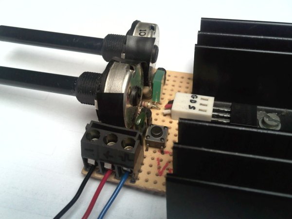
What the PWM driver does:
The driver is fed by a 12V power supply (a regular DC adapter). This DC voltage is chopped into pieces by our MOSFET because it rapidly switches the 12V on and off. This switching is controllable by two potentiometers. One for the ON-time and one for the OFF-time.
If the ON-time and the OFF-time are equal, the output voltage will be 6V.
If the ON-time is larger then the OFF-time, the output voltage will be between 6V and 12V
If the ON-time is smaller then the OFF-time, the output voltage will be between 0V and 6V.
So with this feature, we can control the average voltage that our primary Flyback coil gets. This will change the output voltage.
When we make sure both potentiometers have the same resistance value, we’ll create a block-wave signal that has the same ON- as OFF-time. Decreasing the resistance (of both potentiometers, at the same time) will increase the frequency of the output signal. Increasing the resistance will decrease the frequency.
For more detail: Simple PWM Flyback driver tutorial
- How does the driver control the output voltage?
The driver controls the average voltage received by the primary Flyback coil by adjusting the ON-time and OFF-time using two potentiometers. - What happens if the ON-time and OFF-time are equal?
If both times are equal, the output voltage will be 6V. - Can I increase the frequency of the output signal?
Yes, decreasing the resistance of both potentiometers at the same time increases the frequency. - What is required to make this project?
You only need basic electronic skills and must follow the instructions; you do not need to understand how a transistor or MOSFET works. - How does changing the resistance affect the signal?
Increasing the resistance decreases the frequency, while decreasing it increases the frequency. - What range of voltages can be achieved with this design?
The output voltage ranges between 0V and 12V depending on the ratio of ON-time to OFF-time. - Does the driver require complex knowledge of electronics?
No, the design is relatively simple and easy to make if you follow the provided instructions.
