Summary of Simplify DC-DC Converter Characterization
DC-DC converters transform DC voltage levels for use in electronics like laptops and phones. Engineers characterize these devices to ensure high efficiency and performance through tests such as line regulation, load regulation, quiescent current, and transient response. The article outlines a typical test setup involving an SMU and an oscilloscope to measure parameters like ripple and turn-on time for both buck and boost converter types.
Parts used in the DC-DC Converter Test Setup:
- SMU (source-measure unit)
- Oscilloscope
- Input voltage source
- Output voltage measurement equipment
DC-DC converters are widely used components that convert DC power from one voltage to another, producing a regulated output voltage. These devices are used in many electronic products, including laptops, mobile phones, and instrumentation. Like any device, DC-DC converters need to be characterized by manufacturers and by engineers evaluating them for a design.
Given the increased pressure to develop products that consume less power, design engineers are looking for ways to increase power conversion efficiencies. Thus, numerous measurements are required to characterize the electrical parameters of DC-DC converters. Tests include:
- line regulation,
- load regulation,
- input and output voltage accuracy,
- quiescent current,
- efficiency,
- turn-on time,
- ripple, and
- transient response.
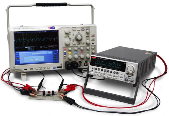
Some of these tests require DC test instruments for sourcing input voltage or current and measuring output voltage and current. You also often need an oscilloscope as well. Figure 1 illustrates a typical DC-DC converter test configuration using an SMU (source-measure unit) and an oscilloscope.
The DC-DC Converter
DC-DC converters can product output voltage that are either higher or lower than their inputs voltages. A step-down (buck) converter produces an output voltage lower than the input voltage while a step-up (boost) converter produces an output voltage higher than the input. Ideally, this conversion should be performed with high efficiency to avoid wasting energy.
Figure 2 is a simplified diagram of a DC-DC converter. The VIN terminal is the input voltage node of the device, which is referenced to the common GND terminal. The VOUT terminal is the regulated voltage output with respect to the common terminal.
For more detail: Simplify DC-DC Converter Characterization
- What is the primary function of a DC-DC converter?
It converts DC power from one voltage to another, producing a regulated output voltage. - How do design engineers increase power conversion efficiencies?
They perform numerous measurements to characterize the electrical parameters of the converters. - Which specific tests are required to characterize DC-DC converters?
Tests include line regulation, load regulation, input and output voltage accuracy, quiescent current, efficiency, turn-on time, ripple, and transient response. - What instruments are needed for some of these tests?
The tests require DC test instruments for sourcing input voltage or current and measuring output voltage and current, along with an oscilloscope. - Does a step-down converter produce a higher or lower output voltage?
A step-down or buck converter produces an output voltage lower than the input voltage. - Can a DC-DC converter produce an output voltage higher than its input?
Yes, a step-up or boost converter produces an output voltage higher than the input voltage. - Why is high efficiency important in DC-DC conversion?
High efficiency is ideal to avoid wasting energy during the conversion process. - What does Figure 1 illustrate in the article?
Figure 1 illustrates a typical DC-DC converter test configuration using an SMU and an oscilloscope.