Summary of Snorecorder with SD Logging
The Snorecorder is a senior design project that detects and records snoring sounds using an ATmega644 microcontroller. It features two recording modes: "trigger" mode logs peak intensity and timestamps for individual snores, while "continuous" mode records audio data at 500Hz to an SD card. The system utilizes a microphone amplifier with hardware filters, an LCD display for real-time feedback, and a four-button interface for user control. Data is saved as CSV files for analysis on a personal computer, helping to study snoring patterns and potential sleep apnea.
Parts used in the Snorecorder:
- STK500 development board (ATmega644 microcontroller)
- Hosiden electret condenser microphone
- Fairchild Semiconductor Operational amplifiers
- National Semiconductor LP2951 5-3.3V Voltage Regulator
- SD Card and Holder
- LCD (16x2 display)
- Four push buttons
Introduction
Sound Byte
The Snorecorder detects snoring sounds from a sleeping person and records the time and intensity of each snore. The data is written to an SD card, which can be easily viewed on a personal computer.
Synopsis
The Snorecorder determines and records snore events and functions in two modes, “trigger” and “continuous”; Trigger mode logs a value of maximum snore intensity and its time stamp for a single snore event, and continuous mode records everything (snores and all) at a rate of around 500Hz, which was the fastest rate we could reliably write to the SD card. Snores are determined by checking a scaled accumulator variable of many analog samples and relating its value to a user-chosen threshold. The snore data is saved as a CSV file to an SD card which can be easily viewed in Excel on a personal computer.
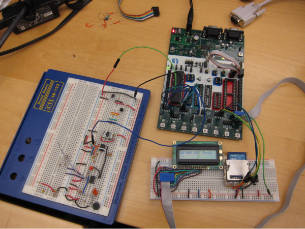
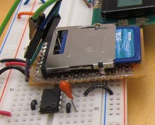
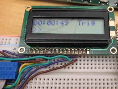
The Snorecorder: microphone located at the bottom corner of the large white board.
Rationale, Inspiration
We chose to build a snore recorder for our senior design project because we were looking to build something that would actually be useful! We felt that Building a health-related device such as a snore recorder would be challenging, yet doable. In fact, we intended the project to be more complex than we were finally able to build (due to time constraints).
Snoring is a common sleep behavior in which obstructed air movement in respiratory cavities (see figure 3) produces moderate to loud cacophonous noise. Snoring causes may include excessive weight, cranio-facial anatomical features and older age[1]. For some, snoring may be a mild health concern, as it tends to cause daytime drowsiness due to sleep deprivation. For others, such as those suffering from sleep apnea, snoring may be more serious as it temporarily stops one from breathing (sometimes for as long as a few minutes) and has been linked to sudden death by cardiac arrest[2][3]. As such, snoring poses an interesting topic of investigation and warrants the development of effective snoring analysis devices. The Snorecorder aims to help study and diagnose snoring and sleep apnea.
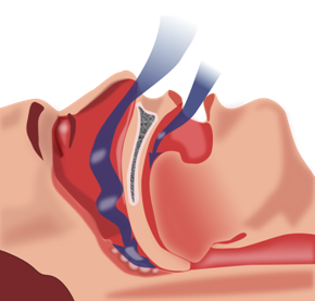
Figure 1: Illustration of blocked airways during sleep, which cause snoring and sleep apnea.
High Level Design
The Snorecorder consists of a high and low passed microphone amplifier circuit, LCD display, button interface, and SD card data storage, which are fed into or are controlled by an atmega644 microcontroller.
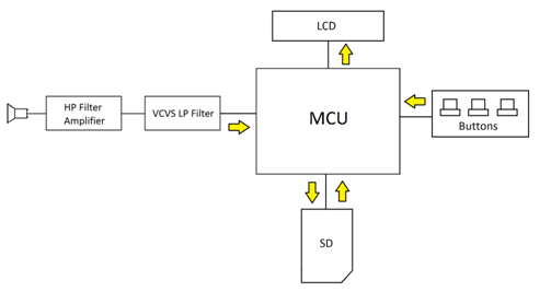
Figure 2: High Level schematic of the Snorecorder
A working microphone amplifier and filter circuit was the first objective of the project. The microphone has a relatively large gain (3000) in order to pick up relatively quiet snores. The amplifier circuit contains first order low pass filters, one which has been chosen for convenience with a 16Hz cutoff and one which has a 60Hz cutoff frequency to partially minimize 60Hz electrical noise. The circuit has a second order voltage-controlled voltage source (VCVS) filter with cutoff frequency centered at 800Hz, which is appropriate for detecting typical snoring frequencies of 100-800 Hz[4]. Without such a low pass filter in hardware, higher frequencies would be accidentally aliased by a software-implemented low pass filter.
The LCD displays the current system time, record/no record mode, and a real-time visual of sound intensity in the form of arrow characters. The button interface consists of 4 buttons and is relatively simple; one button activates “record single event mode,” while another activates “record all”. The other two buttons control the sound threshold at which the Snorecorder uses to determine when a snore occurs relative to background noise.
The SD card, the most difficult-to-implement aspect of the project, is written to by the microcontroller using the FAT file system which is recognized by personal computers. Writing in the FAT file system as opposed to writing individual bytes of memory was chosen as a matter of convenience for the user and as a more elegant solution for uploading snore data than the alternative of transferring bytes by serial connection to a computer.
The microcontroller is responsible for determining snore occurrences, updating the LCD, determining button pushes, and writing to the SD card. A fourth order Cascaded Integrator-Comb (CIC) filter was implemented in software in order to low pass and down sample the signal from 8 KHz to 2 kHz. The CIC result was then filtered again by a second order Butterworth filter (in software) in order to flatten – or make more consistent- the frequency response of the CIC filter.
Math Background
The Snorecorder must be able to differentiate between snores and other sounds, so a firm understanding of snore sounds is essential. Our initial plans for the project were to design a snore recorder specifically to help analyze sleep apnea, but our final project did not differentiate between the two. There are in fact noticeable differences between typical snoring and snoring due to obstructive sleep apnea (OSA). Typical snoring contains noticeable harmonics, while OSA snoring does not, as seen in figure 3.
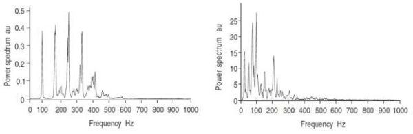
Figure 3: (a) Snore frequency response of a typical snorer and (b) of a snorer suffering from (obstructive) sleep apnea. Typical snoring has clear harmonics in the lower hundreds of hertz, while sleep apnea snores are not harmonic and are mostly below 200Hz.
Also evident in figure 3 is the fact that OSA snorers have significantly lower frequency snores than their typical snorer peers. Our project ended up using a hardware bandpass of 60 to 800Hz. Our project clearly accommodates typical snoring, but the 60Hz would attenuate some of the OSA snorer’s intensity. We did not feel that this was significant attenuation, considering that a typical OSA snorer’s most intense snores are at (slightly) higher frequencies.
Besides hardware filters, we implemented a 4th order CIC filter and a 2nd order Butterworth filter, as mentioned earlier. Both of these functions were borrowed directly from Bruce Land’s tutorial on the ECE4760 course website. The CIC filter is a form of low pass finite impulse response filter which is “cheap” on processing power because it requires only addition and subtraction; it implements a comb filter with a down-sampling integrator. We down-sampled (and rectified) the 8KHz ADC in order to turn the microphone’s signal into the form of a power spectrum. This allowed us to clearly determine periods of loud (more powerful) sounds and periods of quiet (less power).
In addition, a running accumulator on the order of 10ms was used to discriminate between continuous loud noises and brief noise spikes; The ADC values after digital filtering were averaged over the accumulator time interval and checked against the user chosen threshold.
Project Hardware/Software tradeoffs
Our project used a relatively simple method of determining if a snore was present, consisting of three main design features; first, hardware and software filter the signal into the appropriate snore bandwidth. Second, an accumulator is used to add stabilizing hysteresis so that short duration sounds of low frequency such as coughs are ignored. Finally, a sound power threshold is checked to determine that a snore has in fact occurred. This snore detection method works, but perhaps not as well as a matched filter, which is designed precisely for the power-frequency profile of snores. Our Snorecorder may still give false positive snore detections if someone were to rustle particularly loudly, or if someone played strong base tones in a floor below. Had we not gotten stuck on debugging the SD card, we would have had ample time to implement smarter snore detection, such as a matched filter.
Standards
Our project used the Recommended Standard 232 (RS-232) serial standard for debugging, as well as the Serial Peripheral Interface Bus (SPI) for synchronous serial data link between the microcontroller and the SD card. Both were invaluable to the project.
Existing Patents/Copy Rights/Trademarks
There are currently a number of snore detection systems which are patented; some using sound to detect snoring, some analyzing electroencephalograms, and others analyzing pressure signals in the nasal mask. In addition, there is an iPhone application currently available called “Snore Sleep Inspector,” which is rather similar to our project; the iPhone app uses a threshold principle to trigger sound recording, which can be played back at a later time. We do not feel that we are infringing on other copy rights or intellectual property, as we did not consult other projects for choosing a particular snore detection implementation and we have no intention of patenting our design.
Hardware Design
The Snorecorder contains the following devices:
– STK500 development board (ATmega644 microcontroller)
– Hosiden electret condenser microphone
– Fairchild Semiconductor Operational amplifiers
– National Semiconductor 5-3.3V Voltage Regulator
– SD Card and Holder
– LCD
STK500 Development Board
The STK500 development board is equipped with an ATmega644 microcontroller clocked at 16MHz. the microcontroller is responsible for converting an analog input signal from the microphone-amplifier-filter circuits into a digital output. The microcontroller is also responsible to detecting button pushes from a user and taking the appropriate action based on those button pushes (i.e. activate recording, toggle between “trigger” and “continuous” mode, and change the intensity threshold). The microcontroller also updates an LCD and writes data to an SD card.
The STK switches SW0-3 were used for the four buttons, and they were connected to pins D2-5.
Hosiden Microphone, Amplifier, High Pass Filter
The microphone used was an electret condenser microphone found in the ECE4760 lab. The microphone was DC biased with 2.2v as specified in its data sheet, and was also connected to a 2.2µF capacitance. The microphone and its amplifier circuit are shown in figure 4 below.
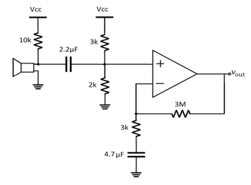
Figure 4: microphone amplifier circuit. Two high pass filters, 60Hz and 11.3 Hz.
The amplifier circuit has a voltage gain of approximately 1000, which was chosen by experimenting with various sound inputs and checking the resulting waveform on an oscilloscope. In figure 4, Vout is fed to the next stage, a VCVS low pass filter, which is seen in figure 5 below.
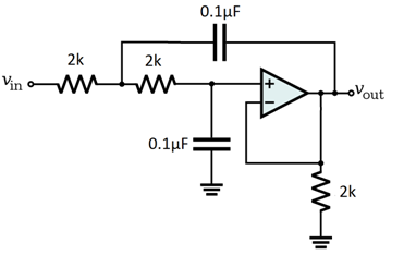
The VCVS filter filters out unwanted high frequency that could possibly be aliased to within our desired frequency spectrum in software filtering. The filter is a second order low pass with cutoff frequency located at approximately 800 Hz, which is appropriate for snoring frequencies. The VCVS filter has a gain of 1, as gain was accounted for in the previous stage.
Our final circuit contained two separate op-amp DIPs, when all we needed was one. Second DIP was used as a matter of convenience during circuit building; it was easier to debug the circuit because the VCVS filter and the microphone amplifier were given plenty of space. Only one opamp should be used in the future.
SD Card and Voltage Regulator
The SD card used was a standard (not high-capacity) 2gb card from Kingston. The card holder was a standard PCB compatible holder. We ran the SD card in SPI mode, which was supported by the ATmega microcontroller family. SCK, MISO, and MOSI are predefined in the ATmega644 datasheet as Pins B7-5 respectively, while pin B4 was used for CS. The microcontroller’s SCK output to the SD card was set up to be 125KHz for starting up and 2MHz for regular writing. The SD card requires a slower clock speed for initializing.
The SD card uses 3.3V logic, so level shifting between the microcontroller’s 5V is important for protecting the SD card. Specifically, pins SCK, MOSI and CS on the SD card need to have level shifted logic in order to avoid hurting the card. (No level shifting is needed on MISO because the microcontroller can read the 3.3V from the SD card). A number of methods of level shifting were tried, and none of them worked consistently or even at all so we decided (after centuries of testing) to not level shift and instead feed the microcontroller’s SPI pins directly to the SD card. It worked! This may shorten the lifespan of the card.
The SD card requires a 3.3V source, so we used an LP2951 5v to 3.3v regulator in order to step down the microcontroller’s voltage to the required level for the SD card. Figure 6 shows the pin setup for the voltage regulator.
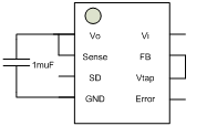
Figure 6: connections for 3.3V voltage regulator.
LCD
The LCD is a standard 16×2 display (16 characters, 2 lines) which was connected to port C on the microcontroller.
Hardware Difficulties
Successfully writing to the SD card was by the far the most difficult hardware (and software) issue that was encountered. On the hardware side, various different voltage shifting schemes were tested; voltage division, diodes and resistors, as well as a level shifter were all tried. These 3 methods failed to work well with our SD card; sometimes the card would be written to, while other times it would completely fail. We were especially surprised to discover that two methods we saw used in previous ECE4760 projects did not work. Voltage division using resistors was used in the Shark Tag project of spring 2008 but it did not work for us. In addition, the resistor and diode setup used in the GPS data logger of spring 2009 did not work either. We even tried a commercial level shifter and it did not work (part ALVC164245). To reinforce the fact that we spent many hours trying to get the SD card to work with level-shifted logic, figures of each level-shift method that we tried are shown below in figure 7:
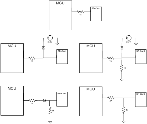
Figure 7: Level shifting schemes that were tested but all failed.
Software Design
The software design aspects are used to communicate between different hardware, and can be divided in to four functional blocks: LCD writing, user interface, digital signal processing, and SD card logging. Although the blocks interact with each other to ensure coherent flow of logic, their functions are relatively independent. The Results section contains example outputs of log files.
LCD Writing
The LCD is being updated every 200ms when recording is turned off and displays the current time in the format of HOUR: MINUTE: SECOND, the recording mode (Continuous or Trigger), as well as a visualize showing the loudness of the input sound. When recording is turned on, i.e. the mcu starts writing to the SD card either continuously or in a triggered fashion, the LCD display is disabled to dedicate the processing power to the SD card writing only. If we do not turn off the LCD display, there will be about 30 ms gap every 200 ms when the SD card is not being written, introducing a large discontinuity in the process. When the recording is being turned off again, the LCD function will resume its normal operation. This scheme will same power as well when ideally the LCD will be unnecessary when the user is sleeping.
User Interface
In addition to the LCD and the serial terminal to give user feedback of the internal operations, we have included four push buttons for the user to interact with the Snorecorder. The button functions are implemented using a de-bouncing subroutine and a series of state machines, and they each control ON/OFF, increase threshold, decrease threshold, and recording mode toggle respectively.
The ON/OFF button will control whether to start logging to the SD card as well as whether to update the LCD. Threshold and recording mode can only be changed when the Snorecorder is in the OFF state, and this is to prevent unwanted adjustments during the recording session that would give results that are inconsistent.
The threshold increase/decrease button changes the threshold point to which the Snorecorder compares the input sound volume. This is designed to calibrate the Snorecorder to the appropriate detection range for loud and quiet snorers.
The recording mode button will toggle between “TRIGGER” and “CONTINUOUS” mode. In TRIGGER, the Snorecorder will log sound values continuously to the SD card at about 500 Hz, high enough to capture any snore content as typical snoring has energy concentrate at 200 Hz and sleep apnea patients has energy concentrate at a lower frequency.
Digital Signal Processing (DSP)
As raw audio signals come in from the ADC, the signal is being processed and logged differently to the SD card depending on the recording mode that was chosen. In order to detect volume and thus the snoring sound, we had to detect the power envelope of the incoming signal. The incoming 8kHz signal is first being rectified by taking the absolute value of its difference with the mean value. The rectified signal is then down-sampled by a factor of 12 through a CIC filter, which is an efficient FIR filtering algorithm which effectively smooths out the rapid transitions and output the envelope of our sound signal. Finally, the power envelope signal is being further filtered using a second-order Butterworth filter. We had to play around with the scaling factor when carrying out the fixed-point multiply just so we get the right amount of amplification.
The analog audio signal is being sampled at 8kHz frequency using an ISR. We chose this number because most of the audio frequency of interest was low passed to 2 kHz in hardware, and an adequate sampling frequency would be about 4 times of the signal frequency. In TRIGGER mode, we only log data to the SD card when we detect a snore. To detect a snore, the volume variable of the Butterworth output is being compared to the threshold volume value set by the user. Once the volume clears the threshold, the ISR starts a peak detection routine for the next three seconds. We set up the mechanism this way under the assumption that a typical breathing cycle will be at least three seconds; therefore, any sound from the next three seconds will belong to the same snore. This is a fair assumption as this would result in a breathing rate of 20 times per second where a typical adult has a breathing rate of 10 to 15 times per second while resting. Once the three seconds timeout, the Snorecorder will log the value of the highest detected volume within the three second window.
In CONTINUOUS mode, SD card operation is run at a frequency of 500Hz. In order to ensure fast writing to the SD card, no additional signal processing is done on the raw ADC values. The data collected is meant to be processed later on a computer terminal.
SD card logging
Writing to the SD card is an integral feature to our project as data could be saved for later analysis. As the SD card communication is done through the SPI ports, we have explored two approaches to writing on the SD card. The first one is to write the complete instruction set to facilitate the interfacing between the SD card and the microcontroller. This would involve sending commands to initialize, write, and read directly the MOSI line, and writing bytes directly into the memory array inside the SD card. However, to read back the data that is logged, we have to dump the data using a serial port as there is no file system inside the SD to be read in an operating system. The second method, the one we used in the project, involves utilizing an existing library for constructing the file system as well as a driver for SD communications. The FatFs library contains methods to create files and writing to the FAT table in an SD card. Familiar functions such as f_open() and f_printf() are used for the file creation and mounting the drive. During the initialization of the SD card mounting, the card must be clocked at a lower frequency at about XTAL/128. After the initialization, we can set the clock to a higher rate although we find lower clocking rates seems to be more reliable.
To ensure proper writing to the SD card, the function get_fattime() has to be implemented. We have implemented with a fixed time string as this is not the focus of our project. A true timestamp could be obtained by writing to the EEPROM of the microcontroller for the system to keep a current time.
Open_log() is invoked when the Snorecorder is turned ON (recording). This function checks the files existing in the SD card and names the new file with a distinct serial number. If the logging mode is in TRIGGER, the function will name the file as STRIGXXX.csv (XXX being decimal numbers), and write the first row of the file to be “Time, Seconds, Strength\n”. If the logging mode is in CONTINUOUS, the function will name the file as SCONTXXX.csv, and write the first row to be “mSeconds, Strength\n”.
Open_log():
switch (record){
case TRIGGER:
do {
snprintf(filePath, 16, “sTrig%03d.csv”, counter);
result = f_open(logPtr, filePath, FA_WRITE | FA_CREATE_NEW);
} while (result == FR_EXIST && ++counter < 1000);
if(f_printf(logPtr, “Time, Seconds, Strength\n”)>0)
break;
case CONTINUOUS:
do {
snprintf(filePath, 16, “sCont%03d.csv”, counter);
result = f_open(logPtr, filePath, FA_WRITE | FA_CREATE_NEW);
} while (result == FR_EXIST && ++counter < 1000);
if(f_printf(logPtr, “mSeconds, Strength\n”)>0)
break;
}
WriteLog() is invoked during the write operation to the SD card. If the logging mode is in TRIGGER, the function will write to the file that’s already opened by open_log() whenever a snore is detected. After that, because the logging is in intermittent fashion, f_sync() is used instead of f_close() to flush the cache in the SD card. This way, if the file were to become corrupt at a later time, the existing data will be saved. If the logging mode is CONTINUOUS, the function will keep writing to the SD card timed by the ISR. F_close() will be called to close the file after the Snorecorder is turned off.
writeLog():
switch (record){
case TRIGGER:
fprintf(stdout, “%d %d\n\r”, zzNow, zzAHA);
if(f_printf(logPtr, “%02d:%02d:%02d, %d, %d \n”, hrs, mins, secs, timeStamp_cur, (zzNow))>0)
break;
else fprintf(stdout, “Log write error.\r\n”);
break;
case CONTINUOUS:
if(f_printf(logPtr, “%lu, %d \n”, ticks, ADCH)>0)
break;
else fprintf(stdout, “Log write error.\r\n”);
break;
//sync the filesystem (flush buffers) so it will power down cleanly
}
Results of Design
Speed of execution
We were generally satisfied with the results of the Snorecorder. Initially intended as a debugging mode, “trigger” mode is useful for logging the number of times one snores during the night and the relative intensity of that snore. It worked well.Figures 8 and 9 contain sample log file outputs for trigger and continuous modes respectively.
For “continuous” mode, we intended to write each ADC value (at a rate of 8kHz) so that the user could look at a waveform of his snoring on a personal computer. However, our major time constraint appeared to be the microcontroller, which could not keep up with the writes that quickly. Part of the problem was that the microcontroller had to update the LCD once every 200ms, which caused a major delay in data logging. Writing to the LCD was therefore disabled when the Snorecorder was activated in “continuous” logging mode. Even after disabling the LCD however, the maximum sampling rate achieved was approximately 500 Hz. This rate is perhaps adequate for snore frequencies up to 250 Hz (based on the Nyquist sampling theory), which means that the recorded signal is adequate for sleep apnea snoring analysis, but is less useful for typical snoring.
Both data logging modes detect loud low frequency sounds as snores. When testing, both modes picked up snores, provided their intensity was above the user threshold. The continuous logging mode was somewhat susceptible to detecting breathing as a snore when the tester breathed heavily on the microphone. The trigger mode was immune to breathing because it ignored all sounds (i.e. breathing) for the next few seconds after a detected snore. The breathing false-trigger is only an issue if the user breaths right at the microphone from a relatively close distance.
Also, the sampled signal produced by continuous mode logging appears to be clipped for very loud snores or sounds. This is understandable, and it can be avoided by positioning the Snorecorder at a slightly further distance from the user. It appears in some of our test waveforms.
| Time | Strength | Seconds |
| 1:54 | 242 | 112 |
| 1:58 | 241 | 116 |
| 2:02 | 182 | 120 |
| 2:07 | 247 | 125 |
| 2:12 | 208 | 130 |
| 2:16 | 169 | 134 |
| 2:22 | 244 | 140 |
| 2:25 | 205 | 143 |
| 2:29 | 242 | 147 |
Figure 8: Sample trigger mode data log, from file “strig001.csv”. The system time is given in mm:ss as well as in number of seconds since start of program. The “strength” field is out of 255.
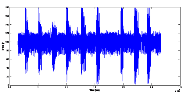
Figure 9: Plot of continuous mode data log, from log file “scont001.csv”. The signal tends to be clipped for excessively loud sounds, as demonstrated.
Source: Snorecorder with SD Logging
-
How does the Snorecorder differentiate between snores and other sounds?
The device uses hardware bandpass filters, software CIC and Butterworth filters, and a running accumulator to check sound power against a user-chosen threshold. -
What are the two recording modes available in the Snorecorder?
The device offers trigger mode, which logs maximum intensity and time stamps, and continuous mode, which records all audio at approximately 500Hz. -
Can the Snorecorder detect sleep apnea snoring?
The hardware accommodates typical snoring frequencies well but attenuates some low-frequency snores associated with sleep apnea due to its 60Hz cutoff filter. -
How is the data from the Snorecorder viewed?
Data is saved as CSV files on an SD card, which can be easily opened and viewed on a personal computer using Excel. -
What frequency range does the hardware filter cover?
The final circuit contains a hardware bandpass filter ranging from 60Hz to 800Hz to detect typical snoring frequencies. -
Why was the LCD display disabled during continuous recording?
The LCD was disabled to dedicate processing power to the SD card writing, preventing delays caused by updating the display every 200ms.