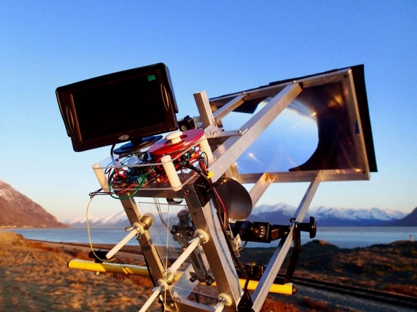
Burning patterns into stuff with the focused suns rays…. about the level of eighth grade earth science before this subject was eliminated by our current Secretary of Education. But what if instead of just killing small arthropods with a death ray and then seeing spots before your eyes for ten minutes you could neatly carve beautiful figures with a solar Etch a Sketch. Controlling the Sun can be done with either moving the beam with a servo-motor mirror system or moving the target. The utility of Laser cutters and CNC machines is demonstrated nearly everywhere–you just need a lot of cash or a nearby well stocked Maker Space to participate in this blooming culture, or do you? The sun is free and the tools to carve into blocks of frozen yogurt or crackers or chunks of wood are easy to obtain from China or Adafruit. This project was done as another instrument to use at Burning Man–the ubiquitous sun, its portability and you can run it for the whole week on a car battery! The output is a little limited–for simplicity sake I designed it to do angles and straight lines but you could jazz it up for circles and curves.
Step 1: Get Your Materials
Adafruit Feather 32u4 Basic Proto –a wonderful little all around board from Adafruit. I have used it in my last several projects and it works flawlessly. I powered the board through the USB.
DC Motor + Stepper FeatherWing Add-on For All Feather Boards works well with the Adafruit feather and since it uses I2C connector it leaves all the other pins free for sensors etc. This board requires a separate power supply for the steppers and is easily setup with another wall wart or another tap off the car battery.
http://www.ebay.com/itm/2-Phases-4-Wires-DC-4-9V-1…I used this setup on the last project https://www.instructables.com/id/Mechanical-Moving…and they are reasonable cost for setting up a cheap, lightweight x-y control system. I have had limited success with speed control on them and you have to be careful to not tax their weight moving limitations. They have a rating at 4 to 9 volts listed and I have never overheated them. These have 20 steps per rotation and 18 degrees/step.
2 axis Joystick–Parallax Inc. Directional control of the suns carving beam–I originally programmed this for speed and direction but since speed control is limited with these steppers I eliminated it.
Light Duty Hobby Servo This is to operate the shutter. You really need a way of turning off the sun else your whole kit will burn up.
https://www.amazon.com/Monitor-GerTong-Universal-W…–the cheapest back-up camera and monitor that you can find. They all can run off a twelve volt battery and they are bomb-proof.
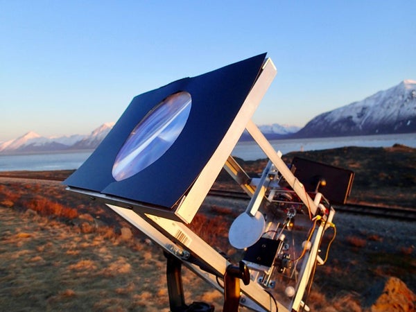
8.3″ x 11.75″ LARGE PREMIUM GRADE Fresnel Lens –these are Fresnel lenses that are used for focusing the suns rays onto your target. Get the slightly more expensive bigger ones. This allows you some latitude in gathering rays if the sun isn’t as strong that day. My experience is here in Alaska in the spring and I had to cover up nearly 3/4 of the lens surface or else the target would burn up.
Step 2: Wiring It Up
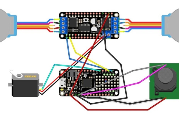
The Fritzing diagram is pretty easy to follow. It is a simple I2C connection between the Stepper Board and the Feather. The power for the board itself comes from the 3 volts on the Feather. The power for the steppers must be provided separately — in this case I was using a car battery for the whole setup so I used a car USB charger for providing power both to the Feather and another line for the Steppers. The car battery also provided power to the back-up camera and monitor. If you are using 110 line voltage you will need a couple different wall warts to provide 12v for the camera unit and 5 volts for the Feather/Stepper Board and Steppers.
The Servo is controlled off of pin 9 on the Feather and I just linked its power to the same source as the steppers. Make sure you use a common ground. The Joystick is connected to A0 and A1 and power and ground on the Feather. The analog inputs sample the voltage from the potentiometers on the joystick and the code controls the x and y directional movement accordingly. You should run the output of the joystick through the serial port just to get an idea that your output mirrors mine or if not set the limits accordingly in the code.
The stepper motors are wired with screw terminals on the Stepper board. As usual make sure that pairs of the matched coils are linked to adjacent screws–they are unmarked on the motor, but a continuity tester will reveal the pairs. Further info and tutorials on all these subjects are available on the Adafruit website. I don’t work for them ( wish I did…) but I have benefitted greatly from their tutorials.
As before I suggest testing the whole unit on a bread board before committing yourself.
Step 3: Building It
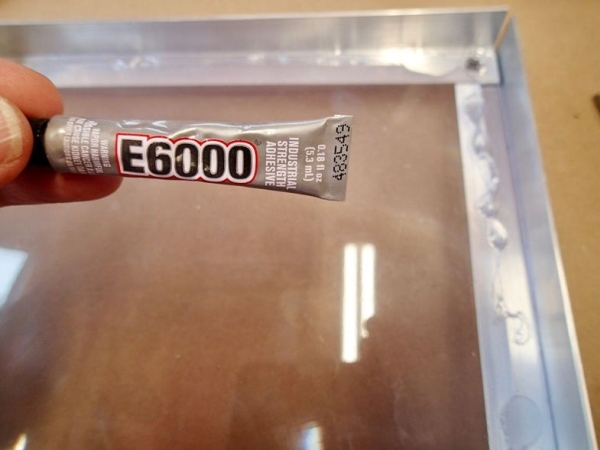
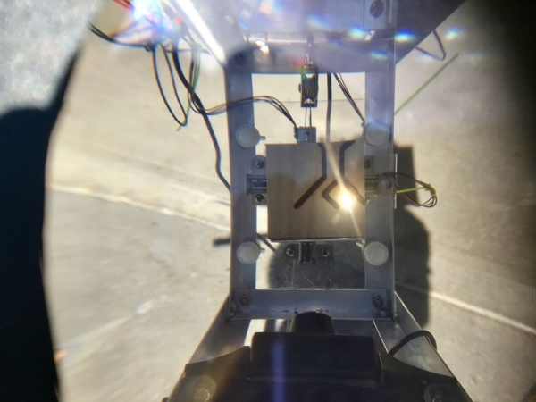
The first step is to frame in the fresnel lens. I use aluminum channel and screws for this construction. The lens panel has to face the sun with groves out. Seal it into the frame with E6000 glue–great stuff. You must determine the focal length for your particular model of lens–mine was exactly 12 inches. You do this in the usual way by imaging an object at optical infinity–the sun and measuring the distance from the screen to where it comes into focus. This is where you will place your x-y gantry. I built mine on plexiglass and mounted it on four spring loaded screws so I could adjust its position for thicker and thinner targets (frozen tofu cakes….) The rest of the frame is constructed around the gantry and lens and provides a location for mounting of the servo controlled shutter. A closeup view of the construction of this linkage is provided. The shutter itself is a cut circle of very thin aluminum–locate it close to the target–you have to move it around to make sure it obstructs the beam well but not too close where it will get hot. The viewing camera I put under the target–it has a very wide field so can pick up the action without being in the way of the beam. I used this camera and monitor setup as you are imaging the sun and it is not a good idea to look at it for any length of time–even with sunglasses. I found that with heavier objects placed on the gantry the vertical stepper had trouble moving so you can see I installed a counterweight pulley system which can be adjusted accordingly.
The electronics bundle with joystick I located on the upper back of the gantry in a plexiglass sandwich with the camera monitor on top–see photo.
Step 4: Programming It
The final code for the Solar Draw has several parts. The drawing portion directs the x-y gantry around in a pattern set up in the first section of the code in dotMatrix. It is a 2 dimensional matrix that lets you describe the movements of the x and y gantry. The number of steps is indicated by the number of rows and the movement of the x and y steppers is described in the 6 column numbers. Column 1 and 2 tell if x and/ or y are moving–designating 1 for yes and 0 for no. Column 3 and 4 tell which direction corresponding x and/or y are moving–1 for forward 0 for backward. Column 5 is total turns of the screw or distance travelled and column 6 is shutter open (1) or closed (0). This lets you program straight or angled lines in as many steps and positions as you want.
int dotMatrix[13][6]={
{1,1,0,0,10,1}, {0,1,0,0,10,1}, {1,1,1,0,10,1}, {1,0,0,0,30,0}, {1,1,1,1,10,1}, {0,1,0,1,10,1}, {1,1,0,1,10,1}, {1,0,1,0,14,0}, {1,1,0,0,5,1}, {1,1,1,0,5,1}, {1,1,1,1,5,1}, {1,1,0,1,5,1}, {1,0,1,0,16,0} };
The setup section of the code executes this pattern once and the loop function sets up control to the joystick. If you want only joystick control you can eliminate this first section. I know there are many Arduino-controlled CNC hardware-software combinations out there and feel free to adapt them to this unit.
The forward/backward adjustment and movement are trial and error when you are setting this up–caused by differences in how the steppers are connected–you basically have to turn the software on to find out which way its going to go and then adjusting it. There are no end stop switches to tell the computer where the x-y gantry is at startup–you can add these if you want to like in my last project. You can adjust this initial position with the joystick and program the gantry to return to the start position when programming the drawing matrix–this will allow you to keep starting the program at the same spot each time.
Step 5: Using It
This is one of those projects where your not sure what is going to happen when you finally line up the sun and turn it on. The first thing was it caught fire. The sun is incredibly strong and the power density at the focal point has to be mitigated by either covering up most of the lens with velcro adjustable screens–see photo above or maintaining the shutter in a closed position while not moving the gantry. Having the shutter closed for a few seconds in between movement excursions allows the substrate to cool down and proceed with your line. Depending on what your lasering–frozen tofu, bread slices, bed sheets or Ant farms you will have different tendencies to fire activity. I was originally going to build the unit with a solar following circuit to mount it on so that it would follow the sun as you were using it, but I found that it was easily mounted on a portable light stand from the big box store and it position relative to the sun could be easily manually adjusted every ten minutes or so. This made it much simpler. If I make it to Burning Man with it this year I will see you out on the Playa.
Source: Solar Draw