Project Introduction
Our project is a spatial audio map of Collegetown that allows the user to use a joystick to virtually travel around the Collegetown crossing area and hear surrounding, directional sound.
Our project takes inspiration from Street View, an interactive technology featured in Google Maps that provides users the ability to visually explore the world through millions of panoramic images along many streets across the globe. With a Virtual Reality headset, a person can have the virtual experience of physically being in that environment. However, this currently lacks an element that we take for granted in our everyday lives: sound. We wanted to make this technology more immersive by offering the user a digital 3D sound experience in a street-view environment.
While currently there are JavaScript-based open-source projects that blend the Web Audio API and Street View together, our project is unique in that we perform all computations that generate the output spatial audio in a microcontroller, as opposed to on the Cloud or some other more powerful but power-hungry microcontroller. In particular, low-power generated spatial audio systems have a promising future in the consumer electronics industry. Battery capacity is a bottleneck for tech companies to put more advanced features into wearable devices such as AR glasses. Generating spatial audio with a microcontroller will directly contribute to reducing the power consumption of the device.
High-Level Design
Logical Structure
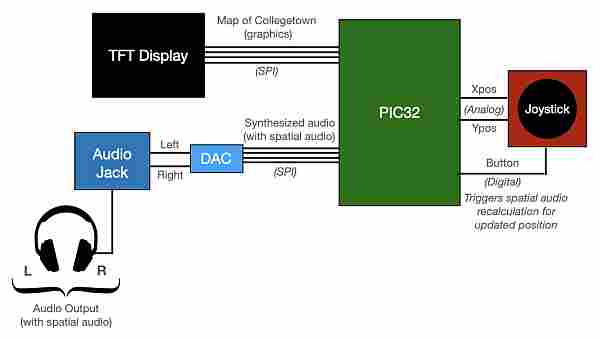
Our project consists of four major functional blocks: (1) the TFT Design (Collegetown map), (2) joystick control, (3) synthesized audio, and (4) spatial audio.
Our user interface consists of a 2D map of one of the major intersections of Collegetown on the TFT display. The user can navigate through the map with a joystick, controlling the position of a green dot that represents the “human” on the map. The position (in terms of x/y coordinates) is then used to determine what sounds the user hears, depending on how close one is too different sound sources.
We implemented three sound sources through Direct Digital Synthesis: the sound of a car engine, a two-toned chime representing Oishii Bowl, and the chirping sound representing a small bird standing on the corner of the intersection. To allow the user to have an immersive spatial audio experience, we used the x/y position from the joystick as an input to a simple head-related transfer function (for directional hearing) and also a sound intensity decay function the further one gets from a sound source.
We tuned the sound intensity decay separately for each sound source so a source like a car has a much larger range where it can be heard than something like a small bird. Additionally, we don’t play any sounds when one is moving around the map. We instead have a button on the joystick to indicate for one to recalculate the spatial audio function and resume playing sounds again.
We then output the calculated sound for our left and right ears to our two DAC channels. By attaching an audio jack and headphones to these two channels, we can hear the directional and spatial audio. Further background information on spatial audio and our synthesized sounds are below.
Hardware/Software Tradeoff
To perform direct digital synthesis on three different audio sources, the major tradeoff is between the sound synthesis frequency and the PIC32 processing speed. In the end, all three localized audios need to be summed together and output into the DAC, the computation needs to happen in the same interrupt service routine. The DDS Interrupt frequency depends on how much computation we need for the spatial audio and determines the highest resolution the audio output can be.
To synthesize more complicated sounds, we need to reduce the ISR frequency which would affect the audio quality. Initially, we were planning to use external storage devices like SD cards or SRAMs to store the raw audio file and perform calibration on the data. However, we encountered some difficulties with the devices, leading us to use direct digital synthesis. We will talk about our experience with SD cards/SRAMs in later sections. The end result we got is 3 different sound sources with an audio sampling frequency of 15KHz.
Background Math
Spatial Audio
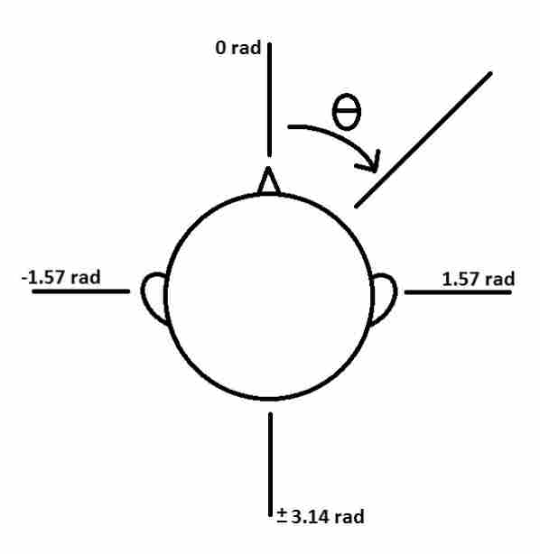
Instead of implementing the complete version of the Head-Related Transfer Function (HRTF), we implemented a simplified version that only takes into account both the delay between left and right channels or interaural time differences (ITD) and the amplitude difference or interaural level differences(ILD). Two main vectors contribute to our math: one from the user’s body center to the sound source and one from the user’s body center to their anterior. According to the 2015 project Sound Navigation, by roughly modeling the user’s head as a sphere with two ears diametrically opposite to each other, we can use the angle between these two vectors to calculate each characteristic interaural difference.
In the timer thread, when the joystick button is pressed, we first calculate the distance between the user’s relative angle to all the sound sources (car, bird, Oishii Bowl). Then plug that number into the two equations above to obtain the amplitude ratio and delay between the two ears. We also use the equation: |Intensity@locA -Intensity@locB| = 20log(dA/dB) to model the intensity of sound decay over distance.
We made the assumption that the synthesized audio has an original amplitude that is the amplitude one would hear within one meter of the sound source and then use that as a reference to calculate the intensity of sound at any other spot on the map. To prove the eligibility of the algorithms, we started by Implementing them with Python on Jupyter notebook. We generated sound to mimic a point sound source from different angles, and, with slight tunings of the head dimension parameters for different users, all experiment users were able to distinguish the sample sound directions.
Synthesized audio
We synthesized our sounds through direct digital synthesis (DDS), decomposing each into digital synthesizable primitives. In particular, we implemented three sounds: the rumble of a car engine, a two-toned bell sound to represent opening the door to Oishii Bowl, and a chirp to represent the presence of a small bird. To mathematically represent the relationship between frequency and sample time for each segment, we approximated each sound’s frequency waveform and amplitude envelope.
To guarantee a steady output of a sound wave, we iterated through the audio sample at a constant speed (with the use of a timer ISR). The ISR we use for DDS is triggered by Timer 2 at ~15kHz synthesis sample rate. This is much lower than the 44kHz we used in the birdsong lab (Lab 1) because of the increased computation time within the interrupt. While this slower sample rate does decrease waveform resolution and means that we are limited in the highest frequency we can generate, we are producing relatively simple sounds that can tolerate these decreases in resolution. One drawback was that we were not able to generate a high-frequency bell sound and instead opted for a two-tone chime, which created a similar effect.
We simulated the audio output of each of our sounds via python scripts within Jupyter notebook before implementing them on the PIC32.
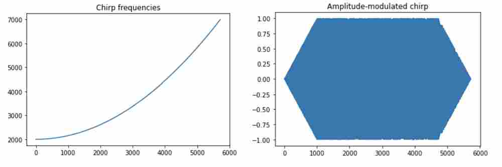
(1) Bird: For the sound of a bird, we used the chirp sound we synthesized during Lab1 which can be approximated as the rising half of a quadratic function as follows. The duration of the chirp is 5720 samples:

The amplitude envelope for the chirp sound is also the same as in Lab 1. It has both an attack time and decay time of 1000 samples as well as a sustained time sample count of 3720.
(2) Oishii Bowl Bell: Our two-toned chime sound was 8000 samples long, with half of the sound having a frequency of 2093 Hz (corresponding to note C) and the other half having a frequency of 1661 Hz (for note G#). We implemented the following amplitude envelope, with the bell having a shorter attack time of 1000 samples, a longer sustain time of 5000 samples, and a decay time of 3000 samples.
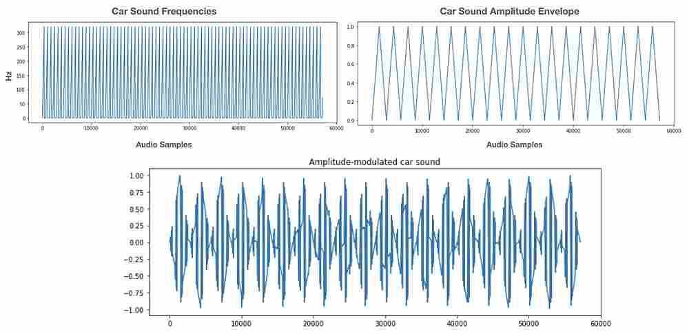
(3) Car: For the car, we have a higher frequency sawtooth frequency waveform with a lower frequency sawtooth amplitude envelope that is slightly out of phase. This allows for the irregularities in the resulting combined audio waveform that resemble the sound of a car engine. For our implementation on the PIC32, we can use piecewise functions to create our sawtooth waveforms. Additionally, the lower resolution from our lower sampling rate actually added some additional distortion that made the sound more realistic (since this sound actually sounds better the more noise there is in the waveform).
Software Design
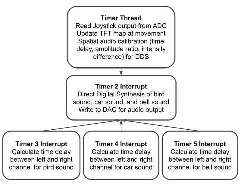
In our final project, we designed the software system based on user interaction. The Timer Thread is responsible for reading user input every 500ms. It first checks the potentiometer output value on the joystick to detect movements. When the user moves the joystick, the audio output stops, and the green dot representing the user on the TFT map moves according to user input. When the user moves the dot to his/her destination, he/she clicks the button on the joystick to start the spatial audio output. Once a button click is detected, the Timer Thread calculates the time delay, amplitude ratio, and intensity difference between the left and right channels for the three sound sources independently.
These changes will be written into global variables which will be picked up by the Timer 2, 3, 4, and 5 Interrupt. Timer 2 Interrupt handles the direct digital synthesis and DAC audio output for the three sound sources. The left and right channels of each sound are calculated independently and summed together to generate the final audio. Because of the spatial audio feature, there will be a delay between the left and right channels. Timers 3, 4, and 5 Interrupts are used to signal the start of the delayed channel for the bird, car, and bell sound.
Timer Thread (Joystick Control and Spatio Audio)
The Timer thread is called every 500 milliseconds. This yield time ensures that joystick movement is smooth from a user perspective but also gives enough time to the thread to finish the calculation. The first task the Timer Thread handles is to read in the two analog values from the x/y position potentiometers on the joystick. If there is a movement indicated by the joystick values, we update the map to show the new “human” position and close timer 2, which is responsible for DDS output. The same process is repeated until the user moves the dot to the destination position and clicks the joystick button. The reason behind this is that performing spatial audio calculation repeatedly will delay the thread response and has a chance to cause a reset on the PIC32.
When the button click is detected, the Timer Thread calculates the parameters related to the spatial audio. Based on the hardcoded sound source positions and the updated “human” position, we are able to determine which ear/channel is further from the sound source, calculate the amplitude ratio and time delay between the left and right channel,s and the intensity difference between the current “human” position and the sound source following the algorithms mentioned above. The intensity difference is represented by the max amplitude of the left or right-channel audio depending on which one is louder and the amplitude ratio is represented by the max amplitude ratio between the further channel and the closer channel. These two values are used to generate the sound amplitude envelope, which will be used in the Timer 2 Interrupt for direct digital synthesis calculation.
The time delay between the two channels is slightly more complicated. To implement the delay, we used timer interrupts to delay the audio starting time of the further channel. This is done by calculating the real-time delay between the left and right ears, converting it to cycle count within the 40MHz PIC32, and setting the interrupt timer to the corresponding value. Every time we finish the audio calibration process in the Timer Thread, a separate timer is started for the delayed audio channel of each sound source when the other channel starts to output the audio signal.
Once the timer finishes counting down, an interrupt service routine is triggered to start audio on the delayed channel. To make sure that we can start the audio on time, we set the DDS Timer 2 ISR to priority 2 and the sound localization ISR to priority 1 so that the DDS calculation will not interrupt the audio calibration. Although this is a simple version of spatial audio only involving intensity and time difference, it can already create the illusion of a sound moving from one side to the other.
Timer 2 ISR (Synthesized Audio)
Timer 2 is used for direct digital synthesis and is opened whenever the button is pressed on the joystick indicating that the spatial audio calibration is recalculated (such as when the “human” has moved on the screen). It is triggered at a constant rate of 15kHz which is our digital synthesis sample rate. Even though digital synthesize sound at this sampling rate will be less realistic than the ones at 44kHz, this is the highest resolution we can achieve when performing DDS on three sound sources at the same time.
In the Timer 2 ISR, we first clear the interrupt flag and compute the frequency functions for each of the three sounds. As stated above, for the bird we approximate a chirping sound with a quadratic function, for the car we use a linear piecewise function to represent a sawtooth waveform, and for the bell, we implement two frequencies to represent a two-toned chime.
For each synthesized audio we call on the DDS algorithm to index into a pre-generated sine table to account for the phase and this sine table entry value is then written into the DAC output. Since frequency has to be positive to produce sound, we leveled the DDS output to make sure it stays at the upper half of the DAC range (0-4096). It is important to note that we compute the frequency functions for each side (left and right) separately as the audio for each ear is different due to spatial audio.
In order to make we synthesized sounds more realistic and also to avoid non-natural clicks, we then layer a different amplitude envelope over each of our sounds as shown in our Synthesized Audio section. We first define an attack time, sustain time, and decay time for each of the three sounds. We then use linear ramp functions to ramp up, ramp down, or sustain the amplitude for a certain number of samples. Like with the frequency functions, we do this for each ear separately. This is also how we implement the intensity difference and the amplitude ratio features of the sound localization. Knowing the max DDS amplitude for each channel, we pre-calculate the ramping up/down the speed in the calibration stage in the Timer Thread and the increment/decrement rate is used here to tune the amplitude.
Lastly, we write these outputs over SPI to DACA and DACB, looping through these sounds until the “human” is moved, which then causes the sound to stop being produced until the button on the joystick is pressed again.
Timers 3,4,5 ISRs
As sound localization requires a delay between two ears to create a sense of direction, we used timers and interrupts to create the delay between DAC channels. In particular, Timer 3 corresponds to the bird sound, Timer 4 corresponds to the car, and Timer 5 is to the Oishi Bowl chime. We determine the further channel and the delay length for each sound source, which will be written into global volatile variables and utilized by the ISRs. After the calculation finishes, timers are started for the delayed audio channels when the closer channels start outputting audio signals.
Once a timer finishes counting down, its corresponding interrupt service routine will be triggered. The ISR first reads the flag indicating whether the left or right channel is further from the sound source. For the selected channel, we apply the amplitude ratio to the max amplitude which is calculated from the ILD equation, and reset the audio output counter of the respective channel to 0 to start the DDS in the Timer2 Interrupt. This process is only done once when the audio output starts. As each channel resets its DDS counter independently, the effect of spatial audio remains when the sounds get looped through in each channel.
TFT Map
To visually present a simplified view of Collegetown showing key elements and sound sources in our intersection, we implemented a graphical user interface on the 320×240 color LCD TFT display. Due to the low resolution of the display, we decided to use a minimalist, flat-design with colorful graphics. Our design consisted of an intersection containing a crosswalk and a road with a dashed centerline, as well as traffic lights, a construction sign, an icon for the Oishii bowl (consisting of a red bowl with rice), a red car, and a yellow bird.
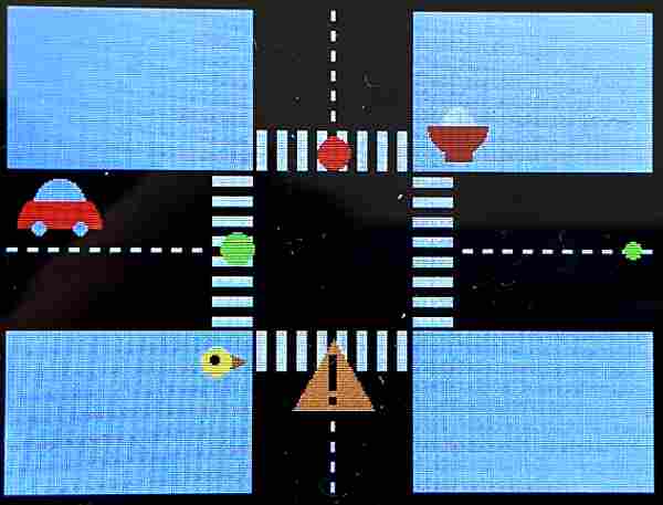
We implemented our map with the tft_gfx library which gave us functions that can draw text and simple geometric shapes such as circles, rectangles, triangles, and lines. To make artistic icons, we strategically overlaid them. The sign for the construction site is two rectangles overlayed on a yellow triangle, the bird is a brown triangle on the side of a big yellow circle with a small black circle for the eye.
For the Oishii bowl icon, we first drew a big red circle. Then covered half of it with a grey rectangle, and then drew a smaller white circle (as the rice). Then covered the second half of that circle with red. The map, we used two big black rectangles as the road and decorated them with dashed lines for the median strip and long skinny white rectangles for the crosswalk. To pick custom colors for our icons, we used an online 16-bit color generator to find the hexadecimal 16-bit color value.
In terms of implementation, we have a function for drawing and initializing the entire map at the beginning of the program. We then have a function for updating the map whenever the “human” moves in order to avoid leaving traces on the road. For example, we redrawn the crosswalk and the road centerline as well as the green traffic light.
Main Function
In our main function, we set up our pins as well as the SPI interface. Additionally, we build the sine lookup table we need for direct digital synthesis, initialize the TFT and college town map, set up the ADC for the joystick, as well as set up system-wide interrupts, protothreads, and our thread scheduling.
Hardware Design
The hardware of the project includes the Course Development Board, its onboard components (the PIC32 microcontroller, MCP4822 DAC, and TFT Display), the PicKit3 Programmer, the audio jack, a pair of headphones, and the joystick.
The PIC32 is a 32-bit peripheral interface controller. It has a high-performance RISC-V core, 2GB of user space memory, up to 5 external interrupts, and support for multiple communication protocols including UART, SPI, and I2C. With the PicKit3 Programmer, we can connect the MCU to a PC and load programs with the MPLABX IDE and XC32 compilers.
The MCP4822 is the dual channel 12-bit Digital-to-Analog Converter (DAC) we use to convert the digital sounds synthesized in the PIC32 to analog audio signals. The DAC receives digital value from the microcontroller through the SPI channel, converts it into an analog waveform, and outputs the signal onto the DACA and DACB pins. We use the audio socket to play the sounds in a pair of headphones, specifically tuning our DAC outputs to work for our specific headphones. We are also able to visualize the output on an oscilloscope for debugging.
The TFT display is a 2.2″ 16-bit color TFT LCD that communicates with the PIC32 through an SPI channel. We use this for displaying our map of Collegetown, and we also used it for printing out debug messages throughout our project as well.
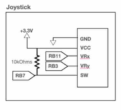
To have our “human” icon navigate throughout the map displayed on the TFT display, we connected a joystick that contains two independent potentiometers (one for each axis, X and Y) as well as an internal pushbutton. The potentiometers are connected to two analog inputs on the PIC32. We added a pullup resistor to make it active low. The pushbutton is connected as a digital input and pressing it indicates to the program that the spatial audio calculations should be recomputed. We use it to recalibrate the sound for the “human’s” change in position on the map. Debouncing is not required since pressing the button multiple times will not affect how our system functions.
Initial + Unsuccessful Attempts and Lessons Learned
Initially, instead of opting for direct digital synthesis, we attempted to store our audio data in the form of .txt files containing analog values of sounds (recorded by us near the Collegetown intersection) that we could write to the DAC. We intended to store these .txt files on a FAT-32 formatted SD card and read the data over SPI using an SD card library created by a former student, Tahmid, for the PIC32. Unfortunately, while we could write into and connect to the SD card, we ran into issues reading more than 512 bytes, which corresponds to one sector in the SD card. Once the pointer for our reader got to 512 bytes, it was unable to continue reading from the next sector of data and instead looped again through the first 512 bytes.
This is an issue since when we created a sample .txt file containing analog values of a 4-second drum beat, that file was already 7MB. There are ways to decrease the size of the file including lowering the sampling rate (which we did) or shortening the length of the sound. However, the gap between what we would like to store and what 512 bytes could provide is still big.
Additionally, it took a significant amount of time to figure out how to have both the TFT and SD card reader work on the SPI channel, as well as set up the library. We conclude that reading/writing from an SD card is a possible approach to one’s project if you only need to store a limited amount of data (up to 512 bytes), though it is a bit tricky to implement correctly. Tahmid’s implementation as well as a previous project using an SD card (PICboy32) are very helpful resources if you choose to use an SD card.
After our attempt with the SD card didn’t work, we attempted to integrate our code with external RAM over SPI. We ran into issues as well, being unable to read/write the correct values. Additionally, the RAM is only 1 kilobit which creates limitations for the audio samples we want to store. We were also unsure of how to post-process this analog data to account for spatial audio after reading it in, so direct digital synthesis ended up being a much better approach.
Read more: SPATIAL AUDIOMAP